


CS-8 ol HDH6/VDL6 Rev1.04, Feb. 2015
-14-
8. MODULE DESCRIPTION
8.1. Layout and functions
Input A
VCF A
Amp
Σ
Stage
1
Stage
2
Stage
3
Stage
4
VCA
Drp A
Stage
5
Stage
6
Σ
Amp
Amp
Amp
6 db
12 db
18 db
24/36 db
Slope
Reso
Input B
VCF B
Amp
Σ
Stage
1
Stage
2
Stage
3
Stage
4
VCA
Drp B
Stage
5
Stage
6
Σ
Amp
Amp
Amp
6 db
12 db
18 db
24/36 db
Slope
Det B
Freq
Det B
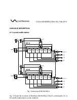
Fig. 3 Structure of HDH6/VDL6
Fig. 3 shows the structure of the filters HDH6/VDL6. The CV-control jacks 10-14
for cutoff and resonance were omitted.
Input:
The audio inputs are signed with
Input A
and
Input B
, these are pure AC
inputs. The controller
Input A
(1) and
Input B
(2) are tied capacitively
decoupled to their input jacks of the same name. The controller attenuate the
incoming audio between 0 and 1.