


SWRU080
Page 2 of 2
7. Setting up a network
•
A fast blinking green/red LED after programming
indicates that the node has no IEEE address.
o
Use the programming interface to
program the IEEE address
o
The IEEE address can be any value
except only FFs
•
The yellow LED is on and coordinator information
is displayed on the LCD when the coordinator
dongle is working . Verify that the LCD is showing
“ZigBee Coord” and “Network ID: 1200
•
Insert each one of the reference nodes in the EB
board and program with the
Reference node
hex
files
•
Place each of the reference nodes on the
SOC_BB boards
•
ZigBee nodes
: The red LED is on when the
nodes connect to the network coordinator
•
TIMAC nodes:
The red LED blinks slowly when
the nodes connect to the network coordinator
•
Insert the blind nodes in the EB board and
program with the
Blind node
hex file. Note that
the blind node must be a CC2431
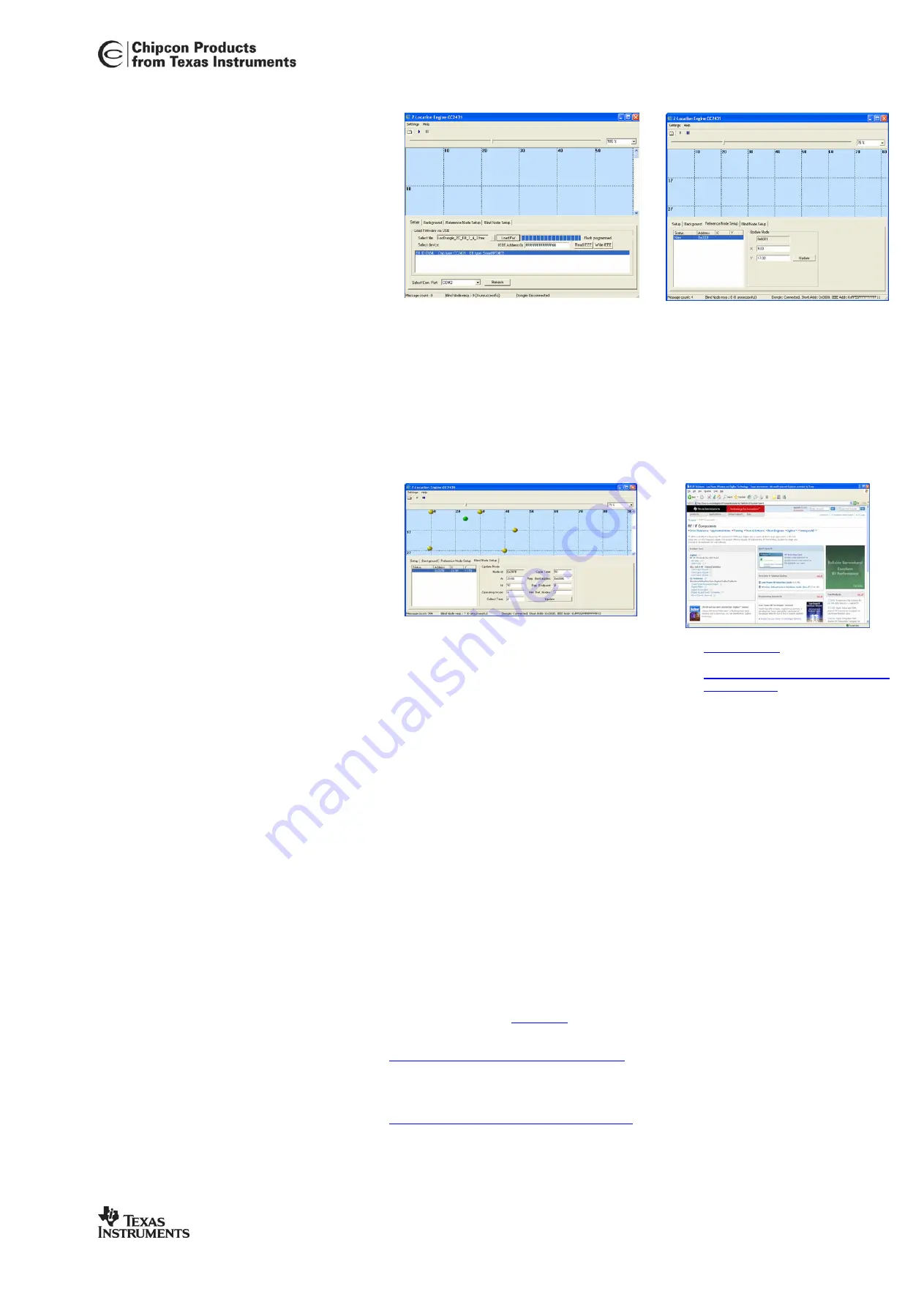
8. Run Z-location engine
•
Make sure the location dongle is powered by
DC power or USB cable and connected to a
PC with RS232 serial cable
•
Start Z-Location Engine, Select Windows
[Start Menu] -> [Programs] -> [Chipcon] -> Z-
Location Engine
•
Select the correct COM port on the bottom of
the screen
•
Start the location engine by clicking the play
arrow on the top toolbar
•
Insert batteries in the SOC_BB boards and
turn on one reference node at a time
9. Setup reference node
•
Select the “Reference Node Setup”
tab in the Z-Location Engine. The
node will be displayed and marked
“new”
•
Double click on the node in the list.
•
Right click in the “blue” location
window at the same place as the
node is located physically. Accept the
new position with the “Update” button
•
Repeat the setup for each reference
node until all nodes are configured
9. Start a blind node
•
After all reference nodes are configured the blind
node can be powered
•
The blind node will automatically be displayed in
the “blue” location window. If the blind node is
moved it will be shown at a new position in the
location window
9. Using the Z-location SW
•
The blind node parameters can be configured
in the blind node tab
•
Cycle time
configures the update rate of the
location in 100ms interval. I.e. 30 gives 3
second update rate
•
Refer to the CC2431DK/ZDK User Manual for
details about other options
10. Documentation
•
www.ti.com/lpw
•
CC2431 product page:
http://focus.ti.com/docs/prod/folders/pr
int/cc2431.html
•
CC2431DK quick start guide
•
CC2431DK User Manual
•
Location engine application notes
10. Technical information
The example code is using 2.4GHz channel 16(0x10)
-
ZigBee code is using PANID 0x1200
-
TIMAC code is using PANID 0x11CC
11. Difference between ZigBee and
TIMAC location systems
The TIMAC location dongle will give nodes short
addresses incrementally starting a 0. The ZigBee
coordinator will give each node unique short
addresses.
TIMAC implements point-to-point communication.
This means that all nodes must be in range of each
other and the blind node must be within range of the
location dongle connected to the PC
The Z-stack location example allows routing of
packets in larger networks where messages can be
routed through several nodes to reach the PC it
reports to.
TIMAC and Z-stack nodes are not interoperable.
Both the 2431ZDK and 2430DK location example
codes are available from
www.ti.com
as source code.
The TIMAC object code can be downloaded from the
TIMAC product page at:
http://focus.ti.com/docs/toolsw/folders/timac.html
The ZigBee location source code is part of the Z-
Stack object code that can be downloaded from the Z-
stack product page at:
http://focus.ti.com/docs/toolsw/folders/z-stack.html
12. Tips
Loading a map as background picture in Z-
location makes it easier to place the reference
nodes without measuring all distances. Use
the background tab and load the map as a
bmp file.


