[DB600] General instruction manual
- 127 -
6-10-2
Cascade control
The instrument (specification with remote signal input) can be used as the secondary controller in a
cascade control loop.
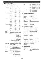
See the following calculation block diagram of cascade control.
.
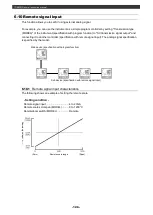
Refer to the following figure as a guide to obtain the cascade input r (ratio) and cascade input b (bias).
A shows a case of r = 1.0, b = a
B shows a case of r = 1.0, b = 0
C shows a case of r = S
1
/S
0
, b = 0
Sensor
Measurement
input
Primary
controller output
PID calculation
Remote signal
input
Cascade
calculation
Output
PV
SV
(Zero)
(Span)
Remote signal input
R
e
m
o
te
s
c
a
le
ra
n
g
e


