


チコーエアーテック株式会社
Copyright CHIKO AIRTEC CO., LTD. 2013
19
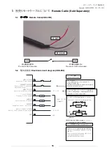
5.3
各線の色と信号について
Color and signal of each wire
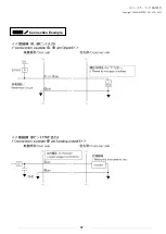
入力
INPUT
・①,④
:接点入力(無電圧接点) Contact input (no-voltage contact)
・ ⑦
:アナログ入力(
0
~
5V
)
Analog
input voltage (0 to 5V)
※
+5.0V
以上印加させないでください。
※
Do not apply voltage exceeding
+
5.0V.
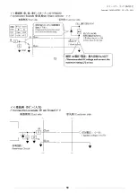
出力
OUTPUT
・③,⑤,⑥ :オープンコレクタ出力
Open collector output
絶対最大定格
Absolute Maximum Ratings
:電圧
(Voltage)
:
50
V ,電流(
Current
):
100 mA
*推奨値: 定格の
1/2
以下
*
Recommended value: less than 1/2 of the rated
・
② :アナログ出力(
0
~
5V
)
Analog output voltage (0 to 5V)
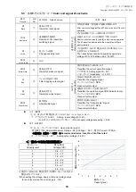
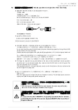
<
7
番ピンの印加電圧閾値表>
能力レベル
Capacity level
電圧
(DCV)
Voltage(VDC)
1
0.6
~
1.1
2
1.2
~
1.7
3
1.8
~
2.3
4
2.4
~
2.9
5
3.0
~
3.5
6
3.6
~
4.1
7
4.2
~
5.0
※誤差が±
4%
ある為、電圧を設定する際は、各レベルの中点の
電圧を印加してください。
*When setting the voltage, apply a mid-point voltage value
for each level since the error range is
±
4%.
線色
Wire color
PIN
NO.
信号名称
Signal
name
役割
Role
黒
Black
①
運転入力信号
Operation input signal
遠隔信号
(
入力
)
Rem
o
te
s
ig
n
a
ls
④⑧を短絡後、①を短絡して運転を開始します
After short-circuiting pins
④
and
⑧、
short-circuit pin
①
to start
operation.
赤
/
白
Red/white
④
遠隔操作切替信号
Remote-control operation
switching signal
④と⑧を短絡してリモート操作に移行させます
短絡するとタッチパネルの操作はできなくなります
Short-circuits the wires [4] and [8] to start remote operation.
The AT panel is disabled while the wires [4] and [8] are
short-circuited.
黄
Yellow
⑦
能力レベル変更
Change capacity level
⑦と⑧の間で、
0~5
Vの電圧を印加する事で能力レベル
を変更することが出来ます。
The capacity level can be changed by applying a
voltage of 0 to 5V between pins
⑦
and
⑧
.
黄
/
白
Yellow /white
⑧
Gnd
黒
/
白
Black/White
②
運転圧力信号
Operation pressure signal
出力信号
O
u
tp
u
t
s
ig
n
a
ls
現在の運転圧力を取り出します
Transfers the current operation output.
アナログ信号
Analog signal
(
0
~
5V
)
インピーダンス
Impedance
(≧
4.7
kΩ)
赤
Red
③
フィルタ目詰出力信号
Filter clogging output signal
目詰まり信号を取り出します
Transfers the clogging signal.
オープンコレクタ出力;
NPN
Open collector output
緑
Green
⑤
運転出力信号
Operation output signal
運転信号(ONランプ)を取り出します
Transfers the operation signal (ON indicator lamp).
オープンコレクタ出力;
NPN
Open collector output
緑
/
白
Green/White
⑥
異常信号
Abnormality signal
異常信号を取り出します
Transfers the ” Abnormality “ signal
オープンコレクタ出力;
NPN
Open collector output
0
0
1
2
3
4
5
6
7
1
2
3
4
5
6
能力レベル
Capacity level
電圧
(DC
V)
V
o
lta
g
e
(VDC
)


