background image

5


別売リモートケーブルについて

5.1 

電気回路図 

Electrical circuit diagram


5.2 

ケーブル 

Remote Cable


⑦(黄)は、他
原因となります

Do not short
Such short
failure.


⑦(黄)は、他の線と短絡しないよう収縮チュ
ーブの中に入っています。 

The wire [7] (yellow) is put inside a shrinkable 
tube so that it cannot be short-circuited with 
other wires.


運転入力信号

遠隔操作切替信号

運転圧力信号

フィルタ目詰信号

運転信号

過負荷信号

サービス電源

GND

Copyright  CHIKO  AIRTEC  CO.,


  10


リモートケーブルについて 

Remote Cable (Sold Separately)

Electrical circuit diagram 

Remote Cable 

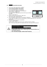
他の線と短絡させないで下さい。

AT

パネルが損傷

となります。


Do not short-circuit the wire [7] (yellow) with other wires.
Such short-circuit may damage the AT panel, and cause 

と短絡しないよう収縮チュ

The wire [7] (yellow) is put inside a shrinkable 

circuited with 

リモート

Remote operation 

リモートモード
(ON 時に遠隔操作可能

Shifting to remote mode
(Remote control is possible in the ON, and the panel 
is impossible to


②圧力アナログ

Pressure 

Temperature correction is not provided.

参照例

インダクター(

(端子番号 3.5.6

F)を付けて下

Attach a  noise limiter (Approximately 33

F)  to the output terminals(Nos.1.2 and 3)
When adding 

インダクタ(リレー等を付加する場合はノイズリミッター

(約33Ω+0.1μ

等を付けて下さい

1

2

3

5

6

8

7

LOAD

LOAD

LOAD

遠隔操作切替信号

フィルタ目詰信号

DC 1〜5V

耐圧 DC 50V

100mmA以下

DC 12V

チコーエアーテック株式会社 

Copyright  CHIKO  AIRTEC  CO.,  LTD.  2009


Remote Cable (Sold Separately)


損傷し、故障の

with other wires. 

circuit may damage the AT panel, and cause 

リモート運転 

Remote operation switch 

リモートモード移行 

遠隔操作可能、この時パネル操作は不可) 

Shifting to remote mode 
(Remote control is possible in the ON, and the panel 
is impossible to control at this time.)


アナログ信号      出力  ≧4.7kΩ    ※温度補正なし 


analog output

  : 

Output impedance 4.7k

Ω


ature correction is not provided.


参照例

Reference


example 

(リレー等)を付加する場合は出力端子

3.5.6)にノイズリミッター(約 33Ω+0.1μ

下さい 

noise limiter (Approximately 33Ω+0.1μ

to the output terminals(Nos.1.2 and 3) 

When adding inductors(such as relays) 

インダクタ(リレー等を付加する場合はノイズリミッター

Ω+0.1μF)又はダイオード

等を付けて下さい

LOAD

LOAD

Summary of Contents for CKU-400AT-HC-V1

Page 1: ...ng saving type clean box that realizes air technology in a compact body ual thoroughly and handle this CKU Series machine correctly so that you can use safely for a long time and enjoy its full perfor...

Page 2: ...losive dust the following substances Flammable substances Gasoline thinner benzene kerosene Aluminum magnesium titanium zinc epoxy etc Dust containing sparks Dust containing sparks generated by high c...

Page 3: ...ctor 8 4 4 Confirmation before operation SK 250AT 450AT 8 4 5 Operation procedure 9 5 Remote Cable Sold Separately 10 5 1 Electrical circuit diagram 10 5 2 Remote Cable 10 5 3 Color and signal of each...

Page 4: ...room temperature ambient temperature 0 to 40 C humidity 80 or less High temperature and dew condensation may cause electrical parts to fail and may cause an electrical shock 100 Provide sufficient spa...

Page 5: ...when the product recover peration without filter or with a clogged and damaged filter may cause trouble because foreign substances enter the blower Install the filter properly before operating the mac...

Page 6: ...ag Exhaust filter Copyright CHIKO AIRTEC CO 5 Name and Structure of Product Name of main body Standard accessories Collecting Adsorbing fine dust and fumes Protecting the circuit and the electrical pa...

Page 7: ...upply The power supply is single phase supply voltage range is 10 The power cable of 3 m with a grounding plug is included AT panel Operating the product with a different power supply may cause burst...

Page 8: ...eases by 1 level Minimum suction level Approximately 60 Hi 1 1 100 Hi switch Every time this switch is pressed the performance increases by 1 level Maximum suction level 100 ON switch and OFF switch t...

Page 9: ...grounding plug are connected correctly insulation is provided properly and the rated voltage is realized Confirm items 1 to 3 above and then proceed to the item 4 AT Turn ON the MAIN POWER switch and...

Page 10: ...ration procedure Connect the power plug to the electrical outlet suction hose hood to a proper position Turn ON the MAIN POWER switch and confirm that the power indicator Press the ON switch to start...

Page 11: ...n the ON and the panel is impossible to Temperature correction is not provided 3 5 6 F Attach a noise limiter Approximately 33 F to the output terminals Nos 1 2 and 3 When adding 33 0 1 1 2 3 5 6 8 7...

Page 12: ...The AT panel is disabled while the wires 4 and 8 are short circuited Yellow white Black White Operation pressure signal Output signals Transfers the current operation output Analog signal 0 5V Impedan...

Page 13: ...in body Transfer required output signals in accordance with the explanation in 5 3 Color and signal of each wire AT ON Lo Hi Change with Lo Hi switch pushing the ON switch of main body AT panel when y...

Page 14: ...the primary filter ter bag replace the secondary filter Make sure to turn OFF the main power and disconnect the power plug from the electrical outlet to cut off the electricity before starting Using a...

Page 15: ...he filter case The filter paper packing of the primary filter is inserted into the cylindrical pipe of the filter case Lightly push down the filter paper packing to remove it snap locks on the left an...

Page 16: ...tion Frequency Description Before operation Is the case closed completely Once day Is the exhaust port unclogged Once day Are no abnormal vibrations generated Is the installation level correct Once mo...

Page 17: ...hat the motor is not overheated by clogged filters 3 30 After checking 1 to 3 above remove the cause of error and press the RESET switch Or turn OFF and ON the MAIN POWER switch to reset the error sta...

Page 18: ...450 100V Single phase 8 2 50 60 7 2 85 73 40 1 dB Note The Noise column indicates a value dB on the scale A at 1 m on the main body side when the hose is connected to the suction port 10 Consumable P...

Page 19: ...ect to change without prior notice Memo about purchase Model Manufacturer s serial number Date of purchase Start of operation Your name Address Phone Person in charge LTD 562 0012 1 1 33 1 1 33 Hakush...

Reviews: