8
Instruction Manual
SMART-LIFT 236 Electric Ceiling Lifts
Installation in a Suspended Ceiling (using threaded rods)
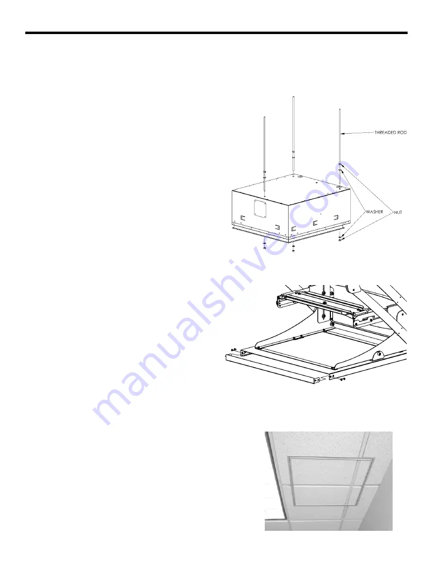
You can suspend the lift housing from three 3/8-in.-dia. threaded
rods (not supplied by Chief Manufacturing) First, secure the rods to
a structural cross brace in the ceiling. Insert the rods through the
three holes on the top side of the lift housing, or through the holes
of optional brackets SMA-651, and secure them to the housing
using two jam nuts (one inside, one outside). See Fig. 3.
CAUTION: For smooth and reliable operation, the lift must be
installed square and parallel in all dimensions. Avoid stressing
or twisting the lift at any time during installation.
Install the lift using threaded rods:
1.
With the lift in the fully retracted position, remove the closure
panel from the bottom of the lift.
2.
If you are using the SMA-651, install it now.
3.
Insert the 3 threaded rods through the top of the lift or
SMA-651.
4.
Using nuts and washers, secure the lift to the threaded rods.
Finish the suspended ceiling:
1.
Cut the grid to fit the perimeter of the lift and insert it into the
side channel of lift (the side channel of the lift will support the
weight of the ceiling grid and tiles).
2.
If using the SMA-620, see the SMA-620 instructions and
install them now.
3.
Cut surrounding ceiling tile to appropriate size.
4.
Make sure the unit is level, square, parallel and there is no
stress applied to the box (chassis).
5.
Using the test push button, carefully operate the lift all the way
up and down to be sure the clearances are adequate. Be pre-
pared to stop the lift immediately if the lift begins to sound
labored or one side begins to travel slower.
6.
Replace surrounding ceiling tile.
7.
With lift at least partway open, remove four screws securing
ceiling tile retainer on bottom of tray (see Figure 4) and
remove ceiling tile retainer.
8.
Cut ceiling tile to fit inside ceiling tile retainer [include grid
pieces if necessary (see Figure 5)] and install ceiling tile (grid)
by sliding it into the open end of the ceiling tile retainer.
CAUTION: Make sure all parts assemble easily, without distort-
ing any parts, when installing tile in the ceiling tray. Any parts
protruding from the tray will cause damage when the unit
closes.
9.
Install ceiling tile retainer and secure using four screws.
Figure 3. Threaded Rod Installation
Figure 5. Grid Intersection
SL236 shown with ceiling tile and grid installed in
bottom panel
Figure 4. Remove Ceiling Retainer


