Installation Instructions
PAC720
5
NOTE:
The faceplate assembly must be attached to the clamp
bracket
below the knob
on the lower part of the cart/
stand post.
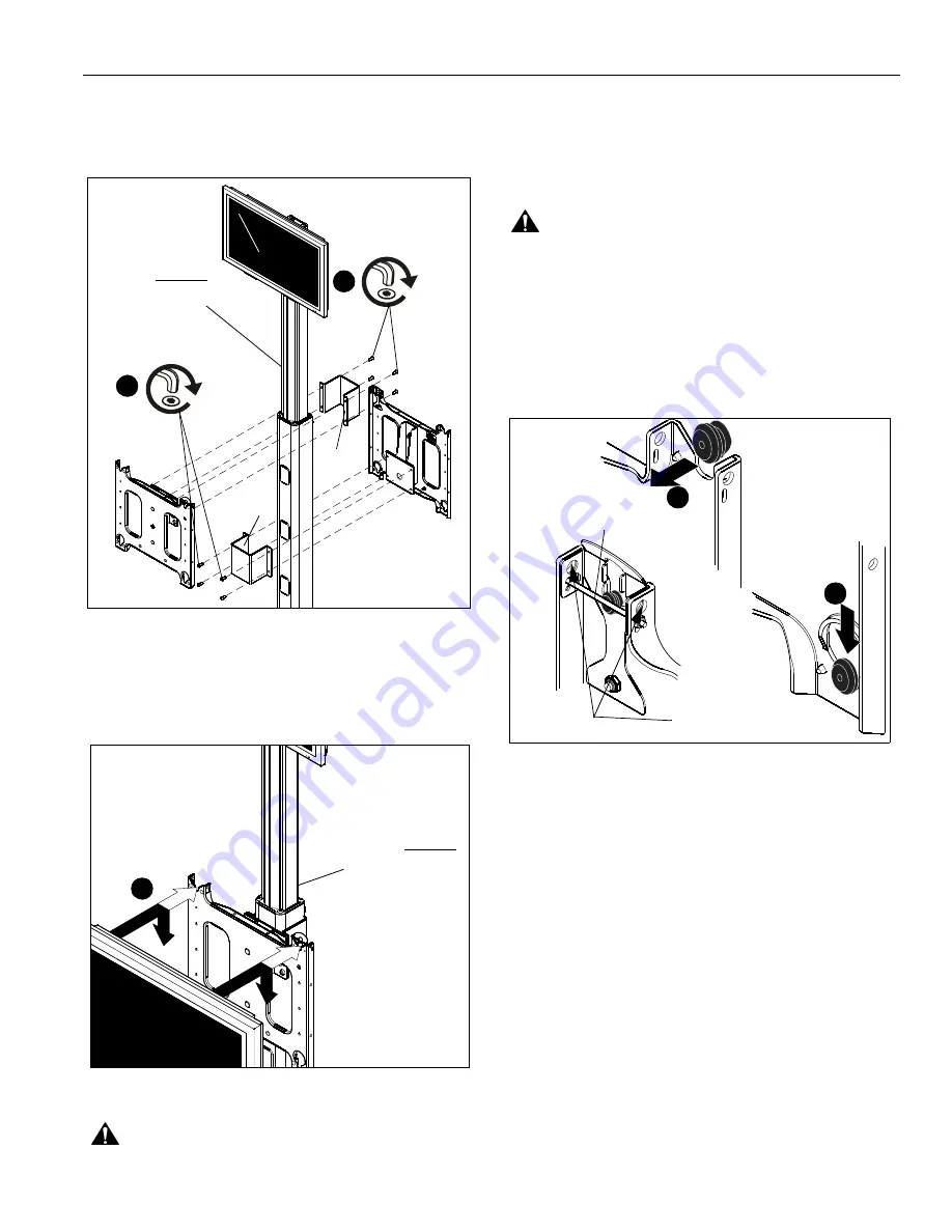
Figure 4
Attaching Display
1.
While supporting both sides of display, align four mounting
buttons on display or interface bracket with four mounting
holes in faceplate. (See Figures 5 and 6)
Figure 5
WARNING:
EACH DISPLAY MAY WEIGH IN EXCESS OF
40 LBS! Always use two people and proper lifting techniques
when installing or positioning display on stand.
2.
Lower display into place listening for audible "click" to
ensure recessed area of mounting buttons are properly
seated in lower area of mounting holes.
(See Figures 5 and 6)
WARNING:
IMPROPER INSTALLATION CAN LEAD TO
CART/STAND OR DISPLAY FALLING CAUSING SERIOUS
PERSONAL INJURY OR DAMAGE TO EQUIPMENT!
Ensure mounting buttons are completely engaged in
mounting holes.
NOTE:
Holes are provided in the faceplate for use with a
padlock or similar locking device, if desired. In addition,
the pin and nut may be removed from the upper holes
and moved to the lower holes for use as a more
permanent locking device. (See Figure 6)
Figure 6
3.
To adjust location of display on cart/stand, support
display(s) and carefully loosen four 5/16-18 x 3/4"
buttonhead cap screws (D) on each faceplate assembly.
4.
Slide display(s) up on post to desired position and tighten
four 5/16-18 x 3/4" buttonhead cap screws (D) for each
faceplate assembly. (See Figures 2 and 4)
5.
Refer to the installation instructions provided with the cart/
stand for further information on
Tilting Display
,
Removing
Display
,
Cable Management
and
Cart/Stand
Maintenance
.
(C)
(C)
3
(D) x 4
3
(D) x 4
PAC720 must be
installed
BELOW
the knob located
on the post back.
(PF2 shown)
1
PAC720 must be
installed
BELOW
the knob located
on the post back.
2
1
Remove pin
and nut and
move to lower holes
A padlock or bolt may
be placed through latch
holes


