


Installation Instructions
PAC501
7
Steel Studs
The exposed portion of the center steel stud must be removed
and the resulting cavity completely framed with steel. The
following steps are suggested. The actual procedure is
dependent upon the specific installation. Refer to the Gypsum
Construction Handbook, Framing - Door and Window Openings
Section for complete details and instructions.
WARNING:
STRUCTURAL FAILURE HAZARD! FAILURE
TO TAKE ADEQUATE PRECAUTIONS CAN LEAD TO
DEATH OR SERIOUS INJURY! Ensure removal of center
stud will not cause unacceptable loss of structural strength.
Consult a qualified building contractor and applicable building
codes.
1.
Remove exposed portion of center steel stud flush with
upper and lower drywall edges.
Figure 3
2.
Cut four 8" long jamb studs out of 25 ga steel stud material.
3.
Using two 2 1/2" drywall screws (not included), attach each
jamb stud to the studs (See Figure 3)
NOTE:
Ensure screws are far enough from block end to
prevent interference with framing screws installed in
In-
Wall Enclosure Installation
section.
4.
If necessary, cut rectangular hole in horizontal framing to
accommodate a UL Listed electrical box accessory (not
included).
5.
Attach 25 ga horizontal steel runner header framing to each
jamb stud with 2 1/2" drywall screws (not included). (See
Figure 3)
In-Wall Enclosure Installation
1.
Install UL Listed electrical box accessory (not included) into
the PAC501 (A) following instructions included with the UL
Listed electrical box.
2.
Connect electrical wiring according to National Electrical
Code (NEC) ANSI/NFPA 70 - 2008, wire connection
requirements.
3.
Route audio/visual cables into housing.
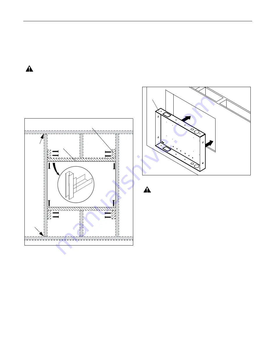
4.
Center PAC501 (A) in opening and insert into opening. Align
front of box with front face of wall. (See Figure 4)
Figure 4
WARNING:
ELECTRICAL SHOCK HAZARD! CUTTING
OR DRILLING INTO ELECTRICAL WIRES OR CABLES
CAN CAUSE DEATH OR SERIOUS PERSONAL INJURY!
ALWAYS make certain area behind mounting surfaces is free
of electrical wires and cables before cutting, drilling, or
installing fasteners.
5.
Drill four 3/16" diameter pilot holes in studs at side mounting
holes. (See Figure 4)
6.
Attach the PAC501 (A) to side studs using four M7 x 50mm
Allen head connector screws (D) and mounting spacers (B)
using an M4 Allen head drill bit (E). (See Figure 5)
Horizontal Framing
Jamb
Studs
Screws
(Typical for each
jamb stud)
(not included)
anchor
to runner
anchor
to runner
Drywall
(4 places)
Mounting
(A)


