Installation Instructions
Model: PAC-200
5
INSTALL PAC-200 COMPONENTS
1.
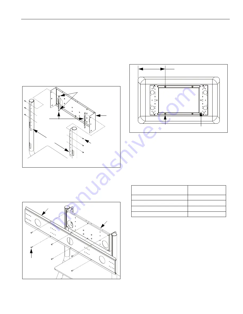
Determine desired height for head (20) keeping in
mind display size and viewing requirements.
2.
Using hex key (60), install six retained 1/4"-20 x 5/8"
button head cap screws through selected fastener
holes in leg brackets, through head (20), into
spreaders (40) (See Figure 4). Tighten securely.
Ensure the following:
•
Head (10) is facing
front
of cart.
•
Spreaders (40) are oriented so that nuts face
inside
of head (10).
Figure 4: Install Dual Mount Head
3.
Using hex key (70), install six screws (50) through
bracket (10), into head (20) (See Figure 5). Tighten
securely.
Figure 5: Install Dual Mount Bracket
4.
If not previously installed, install interface (not
included) to each display. See instructions included
with interface.
5.
Lay display face down on protective surface.
Measure from side edge of display
case
(not display
screen) to center of nearest display mounting button
on interface (See Figure 6).
Figure 6: Mounting Button Measurement
6.
Using measurement from previous step, determine
mounting holes to be used in bracket (10) from the
following table:
NOTE:
The following table assumes that displays are
symmetrical and of equal size. If they are not,
adjust location accordingly.
7.
Using hex key (60), install four of the retained
1/4"-20 x 5/8" button head cap screws through
retained faceplate/side bracket assembly into
appropriate set of mounting holes in bracket (10) (See
Figure 7). Tighten securely.
1/4"-20 x 5/8"
Screws (6 places)
Leg Brackets
NOTE: Upper assembly lines shown; middle and
lower assembly lines similar (not shown for clarity).
20
40
Nuts (right side shown;
left side similar)
50
(6 places)
10
20
IF mounting button measurement is: THEN use bracket (10)
mounting holes:
11-7/8" or less
Set 1 (inner holes)
More than 11-7/8" and up to 12-7/8"
Set 2
More than 12-7/8" and up to 13-7/8"
Set 3
More than 13-7/8" and up to 14-7/8"
Set 4 (outer holes)
Measure this distance
Mounting buttons
(4 places)
Interface


