background image

Installation Instructions

Model: MSP-DCCFTP-Series

5

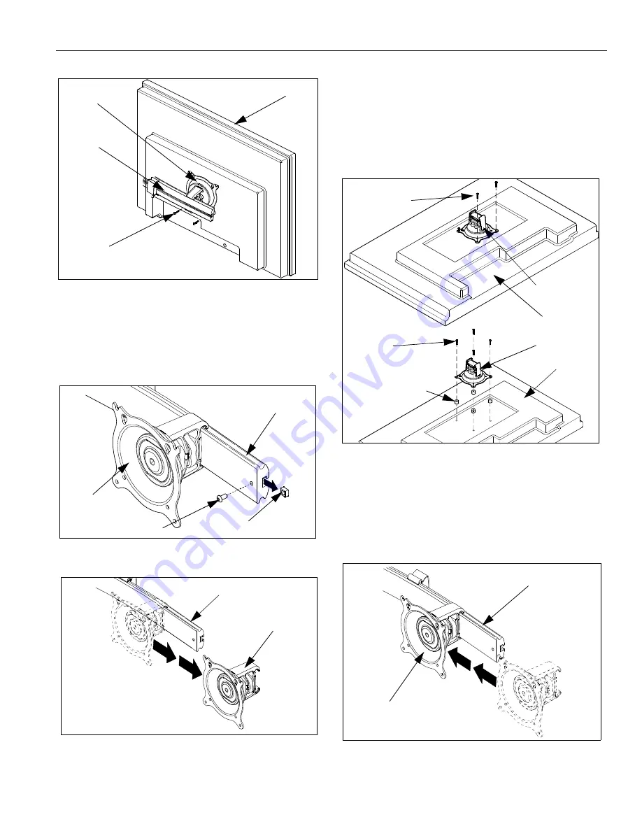
Figure 7:  Secure Display to Centris Bracket

Attach Centris Head to Recessed Mount Display

1.

Uninstall end lock using the 5/32" hex key (80).
(see Figure 8)

2.

Remove Centris head from array rail (10, 20, 180).

Figure 8:  Remove End Lock(s)

Figure 9:  Slide Centris Bracket off Array Rail

3.

Place display face down on a clean dry surface.

4.

Place four nylon spacers (130) over four mounting
holes in display back (see Figure 10).

5.

Align Centris head mounting holes with four nylon
spacers (130) (see Figure 10).

6.

Secure Centris head to display using four
M4 x 10mm or four M4 x 20mm Phillips Pan Head
Screws (110 or 120) and four spacers (130).
(see Figure 10).

Figure 10:  Mount Centris Bracket to Display

7.

Slide display with Centris bracket onto array rail
(10, 20, 180) (see Figure 11).

NOTE:

Repeat previous steps for each additional display.

8.

Reinstall end locks into mounting rail using the 5/32"
hex key (80) (see Figure 12).

Figure 11:  Mount Display with Centris Bracket to

Array Rail

Display

Centris Head

(10, 20, 180)

(110)

Square Nut

End Lock

Centris Head

(10, 20, 180)

Centris Head

(10, 20, 180)

Display

Centris Head

Spacer (130)

(120)

Centris Head

Display

May be required
in deeper recesses

(110)

(10, 20, 180)

Display with Centris Bracket
(Display not shown)

Summary of Contents for MSP-DCCFTP-Series

Page 1: ... displays DCCFTP 320 DCCFTP 440 DCCFTP 220 DCCFTP 221B DCCFTP 441B CAUTION To prevent damage to the Kit which could affect or void the Factory warranty and to the equipment that will be attached to it thoroughly study all instructions and illustrations before you begin the installation CAUTION Exceeding the weight capacity can result in serious personal injury or damage to equipment It is the inst...

Page 2: ...SEMBLY Triple 1 30 BASE Freestand 1 1 1 1 1 40 POLE Freestand 14 1 1 1 50 POLE Freestand 28 1 60 SHEATH Cable Management 8 1 1 2 1 2 70 SCREW Freestand Pole Mounting 3 8 16 x 1 FHCS 1 1 1 1 1 80 KEY Hex 5 32 1 1 1 1 1 90 N A 100 KEY Hex 7 32 1 1 1 1 1 110 SCREW Phillips Pan Head M4 x 10mm 8 12 16 8 16 120 SCREW Phillips Pan Head M4 x 20mm 8 12 16 8 16 130 SPACER Nylon 3 8 used with item 120 8 12 1...

Page 3: ...pads 140 to bottom of base 30 locating pads See Figure 3 Figure 3 Install Rubber Pads FTP 220 320 440 221 441 Assembly To assemble the FTP 220 320 440 221 441 1 Assemble pole see note below to base 30 using one 3 8 16 x 1 FHCS 70 see Figure 2 NOTE For FTP 220 FTP 221 FTP 320 use pole 40 For FTP 440 use pole 50 For FTP 441 use pole 190 40 50 190 100 30 70 140 30 Figure 1 Parts 10 20 30 40 50 70 150...

Page 4: ...cluded in the kit DO NOT use the screws provided Using the wrong screws could result in damage to your monitor 1 Install two M4 x 12mm Phillips pan head screws 110 into two upper mounting holes in display back see Figure 5 NOTE DO NOT fully tighten at this time 2 Hang display on Centris head see Figure 6 3 Install bottom two M4 x 10mm Phillips pan head screws 110 through Centris head mounting hole...

Page 5: ...ee Figure 10 6 Secure Centris head to display using four M4 x 10mm or four M4 x 20mm Phillips Pan Head Screws 110 or 120 and four spacers 130 see Figure 10 Figure 10 Mount Centris Bracket to Display 7 Slide display with Centris bracket onto array rail 10 20 180 see Figure 11 NOTE Repeat previous steps for each additional display 8 Reinstall end locks into mounting rail using the 5 32 hex key 80 se...

Page 6: ...13 Display Horizontal Adjustment Display Pitch and Roll Adjustment To adjust display pitch or roll position 1 Loosen Centris bracket front adjustment knob see Figure 14 2 Tilt display up or down or adjust display roll left or right until properly positioned 3 Tighten Centris bracket front adjustment knob Figure 14 Display Pitch and Roll Adjustment CABLE MANAGEMENT The FTP Series mount includes cab...

Page 7: ...Installation Instructions Model MSP DCCFTP Series 7 ...

Page 8: ...Model MSP DCCFTP Series Installation Instructions 8 ...

Reviews: