background image

LDB1U

Installation Instructions

8

Attaching Screen to Mount

IMPORTANT ! :

Position screen in a centered position on

rails.

NOTE:

NEVER place both interface brackets (T and U) to one
side of the wall mount center line! (See Figure 8)

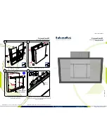
Figure 8

1.

Hang screen onto the top rail of the table stand interface (S).
(See Figure 9)

Hang top hook of interface brackets (T and U) onto the
top rail of the table stand interface (S). (See Figure 9)

NOTE:

The screen initially installs into the "service mode" to

allow easy cable access.

2.

Adjust screen and rails to desired viewing position.

3.

Route cables between wall and rails.

CAUTION:

PINCH POINTS! Keep fingers, hands and

cables out of pinch point areas.

4.

Pull downward on the pull cords and swing inward toward
wall, latching interface brackets to lower rail and fastening
bottom of screen to the mount. (See Figure 9)

5.

Attach end of pull cord (a magnet) to mount so it does not
extend beyond bottom of screen. (See Figure 9)

Figure 9

Locking Screen Interface Brackets (Optional)

1.

Lock screen interface brackets onto mount rails using one
3/8-16 x 3/4" set screw (P) on each interface bracket. (See
Figure 10)

Figure 10

NEVER place both interface brackets to one
side of the wall mount center line (CL)!

Center Line (CL)

[Brackets T and U shown]

5

 Pull

1

Top
Hook

cords

4

4

1

(P) x 2

Summary of Contents for LDB1U

Page 1: ...I N S T R U C T I O N S Large Bolt Down Table Stand Spanish Product Description German Product Description Portuguese Product Description Italian Product Description Dutch Product Description French P...

Page 2: ...ruction of equipment if you do not follow the corresponding instructions IMPORTANT SAFETY INSTRUCTIONS WARNING Failure to read thoroughly understand and follow all instructions can result in serious p...

Page 3: ...Installation Instructions LDB1U 3 DIMENSIONS...

Page 4: ...l Chave de bocas Chiave a punte aperte Steeksleutel Cl fourche By Hand A mano Von Hand Com a m o A mano Met de hand la main Hex Head Wrench Llave de cabeza hexagonal Sechskantschl ssel Chave de cabe a...

Page 5: ...rface AA 1 Clamping plate W 4 1 4 20 x 1 2 X 1 Cable port cover Y 1 3 16 BB 3 1 4 20 x 2 1 2 CC 3 1 4 C 4 E 4 A 4 M4x12mm B 4 M4x20mm M4x25mm D 4 M5x12mm M5x20mm F 4 M5x25mm G 4 M6x12mm H 4 M6x20mm Un...

Page 6: ...age to equipment The mounting surface must be a minimum of 3 4 in depth for medium density fibreboard or particle board If mounting to another type of surface make sure surface can hold up to four tim...

Page 7: ...he diamond shape holes in the bracket correspond to the center of the mount WARNING IMPROPER INSTALLATION CAN LEAD TO DISPLAY FALLING CAUSING SERIOUS PERSONAL INJURY OR DAMAGE TO EQUIPMENT Using screw...

Page 8: ...ewing position 3 Route cables between wall and rails CAUTION PINCH POINTS Keep fingers hands and cables out of pinch point areas 4 Pull downward on the pull cords and swing inward toward wall latching...

Page 9: ...11 NOTE The padlock maximum shackle diameter is 5 16 7 9 mm Figure 11 Additional Mount Safety If LDS1U is mounted to a table in a high traffic area it is recommended that a safety strap be used for a...

Page 10: ...LDB1U Installation Instructions 10...

Page 11: ...Installation Instructions LDB1U 11...

Page 12: ...18 Europe A Franklinstraat 14 6003 DK Weert Netherlands P 31 0 495 580 852 F 31 0 495 580 845 Asia Pacific A Office No 918 on 9 F Shatin Galleria 18 24 Shan Mei Street Fotan Shatin Hong Kong P 852 214...

Reviews: