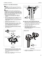
CHIEF CPA116 Installation Instruction Download Page 2

CPA116

Installation Instructions

2

DISCLAIMER

Milestone AV Technologies and its affiliated corporations and
subsidiaries (collectively "Milestone"), intend to make this
manual accurate and complete. However, Milestone makes no
claim that the information contained herein covers all details,
conditions or variations, nor does it provide for every possible
contingency in connection with the installation or use of this
product. The information contained in this document is subject
to change without notice or obligation of any kind. Milestone
makes no representation of warranty, expressed or implied,
regarding the information contained herein. Milestone assumes
no responsibility for accuracy, completeness or sufficiency of
the information contained in this document.

Chief® is a registered trademark of Milestone AV Technologies.
All rights reserved.

 IMPORTANT SAFETY INSTRUCTIONS

WARNING:

A WARNING alerts you to the possibility of

serious injury or death if you do not follow the instructions.

CAUTION:

A CAUTION alerts you to the possibility of

damage or destruction of equipment if you do not follow the
corresponding instructions.

WARNING:

Failure to read, thoroughly understand, and

follow all instructions can result in serious personal injury,
damage to equipment, or voiding of factory warranty! It is the
installer’s responsibility to make sure all components are
properly assembled and installed using the instructions
provided.

WARNING:

Failure to provide adequate structural strength

for this component can result in serious personal injury or
damage to equipment! It is the installer’s responsibility to
make sure the structure to which this component is attached
can support five times the combined weight of all equipment.
Reinforce the structure as required before installing the
component. The ceiling to which the mount is being attached
may have a maximum drywall thickness of 5/8” (1.6cm).

WARNING:

Exceeding the weight capacity can result in

serious personal injury or damage to equipment! It is the
installer’s responsibility to make sure the combined weight of
all components located within the mounting system of the
CPA116 does not exceed 75 lbs (34.02 kg).

The weight capacity of the CPA116 may be LIMITED to
the lowest weight capacity of any other component or
accessory used within the mounting system.

WARNING:

Use this mounting system only for its intended

use as described in these instructions. Do not use
attachments not recommended by the manufacturer.

WARNING:

Never operate this mounting system if it is

damaged. Return the mounting system to a service center for
examination and repair.

WARNING:

Do not use this product outdoors.

NOTE:

Accessory is intended to be used with the UL Listed

CPA Extension Column Series (not included) and
RPEU, RPEUW, RPMEU, RPMEUW, RSEU, RSEUW,
RSMEU or RSMEUW projector mounts (not included).

IMPORTANT ! :

These CPA mounts are designed to be:

mounted to a double 2" x 4" wood framework
ceiling;

mounted to an 8" concrete ceiling;

mounted to a suspended metal framing channel
ceiling.

WARNING:

Do NOT attach to vertical mounting surfaces

such as walls or angled ceilings!

--SAVE THESE INSTRUCTIONS--

Summary of Contents for CPA116

Page 1: ... N L E I T U N G Flat Pin Connect Ceiling Plate Plaque de connexion par goupille plate pour plafond Flache Deckenplatte für Steckverbindung Spanish Product Description German Product Description Portuguese Product Description Italian Product Description Dutch Product Description French Product Description CPA116 ...

Page 2: ...uate structural strength for this component can result in serious personal injury or damage to equipment It is the installer s responsibility to make sure the structure to which this component is attached can support five times the combined weight of all equipment Reinforce the structure as required before installing the component The ceiling to which the mount is being attached may have a maximum...

Page 3: ...6 concrete AF8 anchors M6 included 1 Install to wood ceiling joists 5 16 x 2 3 4 minimum length lag screws Qty 4 2 Install to threaded rod 3 8 ASTM A307 threaded rods 16 threads square inch Qty 4 3 8 channel nuts Qty 4 3 8 jam nuts Qty 8 3 8 washers Qty 8 3 Install to solid concrete UX10 or AF8 anchors Qty 4 5 16 flat washers Qty 4 5 16 x 2 3 4 bolts Qty 4 A 1 CPA116 Ceiling Plate H 1 M6 B 1 Ceili...

Page 4: ...ano Met de hand À la main Hex Head Wrench Llave de cabeza hexagonal Sechskantschlüssel Chave de cabeça sextavada Chiave esagonale Zeskantsleutel Clé à tête hexagonale Pencil Mark Marcar con lápiz Stiftmarkierung Marcar com lápis Segno a matita Potloodmerkteken Marquage au crayon Drill Hole Perforar Bohrloch Fazer furo Praticare un foro Gat boren Percez un trou Socket Wrench Llave de cubo Steckschl...

Page 5: ...ceiling WARNING Do NOT attach to vertical mounting surfaces such as walls or angled ceilings WARNING IMPROPER INSTALLATION CAN LEAD TO LIFT FALLING CAUSING SEVERE PERSONAL INJURY OR DAMAGE TO EQUIPMENT It is the installer s responsibility to make certain the structure to which the mount is being attached is capable of supporting five times the weight of the CPA mount and all attached equipment Rei...

Page 6: ...Installing to a Suspended Ceiling NOTE The CPA mount may be suspended from four 3 8 in diameter threaded rods not included which are secured to a 1 5 8 x 1 5 8 12ga metal framing strut channel spanning a maximum of 4 feet not provided by 3 8 channel nuts not included Threaded rods must have 16 threads per square inch 1 Insert the rods into the four bolt holes in the CPA mount 2 Secure the threaded...

Page 7: ...o four drilled holes See Figure 7 4 Loosely install two 5 16 x 2 3 4 bolts not provided through two 5 16 flat washers not provided into opposite anchors See Figure 7 5 Place ceiling plate A up to ceiling and turn until bolts hold plate up in position See Figure 7 Figure 7 6 Install two 5 16 x 2 3 4 bolts not included through two 5 16 flat washers not included through holes on ceiling plate A and i...

Page 8: ...urale inadéquate pour ce composant peut entraîner de graves blessures corporelles ou endommager l équipement Il est de la responsabilité de l installateur de s assurer que la structure à laquelle ce composant est attaché peut supporter cinq fois le poids total de l équipement Si nécessaire renforcez la structure avant d installer le composant Le plafond sur lequel le support est fixé doit avoir un...

Page 9: ...allez aux solives de plafond en bois Vis tire fond de 8 mm x 7 mm 5 16 x 2 3 4 longueur minimum Qté 4 2 Installez à une tige filetée Tiges filetées de 9 5 mm 3 8 ASTM A307 16 filetages pouce carré Qté 4 Écrous crénelés de 9 5 mm 3 8 Qté 4 Contre écrous de 9 5 mm 3 8 Qté 8 Rondelles de 9 5 mm 3 8 Qté 8 3 Installez à un béton solide Vis d encrage de UX10 ou AF8 Qté 4 Rondelles plates 8 mm 5 16 Qté 4...

Page 10: ...le comme des murs ou des plafonds coudés AVERTISSEMENT UNE MAUVAISE INSTALLATION PEUT PROVOQUER LA CHUTE DE L ÉLÉVATEUR ET ENDOMMAGER CELUI CI VOIRE ENTRAÎNER DES BLESSURES CORPORELLES GRAVES Il est de la responsabilité de l installateur de s assurer que la structure à laquelle le support est fixé peut supporter 5 fois le poids de l ensemble constitué par le support du CPA et le matériel qui y est...

Page 11: ...re 5 Figure 5 Installation à un plafond suspendu REMARQUE Le support CPA peut être suspendu à l aide de quatre tiges filetées d un diamètre de 9 5 mm 3 8 non incluses arrimées à un profilé métallique de calibre 12 de 4 2 cm x 4 2 cm 1 5 8 x 1 5 8 d une longueur maximale de 122 cm non fourni par des contre écrous de 9 5 mm 3 8 non fournis Les tiges filetées doivent avoir 16 fils par pouce carré 1 I...

Page 12: ... 7 4 Installez librement les deux boulons 8 mm x 7 mm 5 16 x 2 3 4 non fournis à travers deux rondelles plates de 8 mm 5 16 non fournies dans les dispositifs d encrage opposés Voir la Figure 7 5 Placez la plaque pour plafond A jusqu au plafond et tournez jusqu à ce que les boulons fixent la plaque en position Voir la Figure 7 Figure 7 6 Installez les deux boulons 8 mm x 7 mm 5 16 x 2 3 4 non fourn...

Page 13: ...u schweren Verletzungen oder Geräteschäden führen Der Monteur hat dafür zu sorgen dass die Konstruktion an der das Bauelement angebracht wird über die erforderliche Tragfähigkeit verfügt Die Konstruktion muss das fünffache Gesamtgewicht des Geräts tragen können Verstärken Sie vor der Montage des Bauelements ggf die Konstruktion Die Gipskartonschicht der Decke an welcher die Halterung befestigt wir...

Page 14: ... mitgeliefert 1 Montage an Holzdeckenbalken 7 9 mm x 12 7 19 mm 5 16 x 2 3 4 Ankerschrauben Minimallänge 4 St 2 Montage an Gewindestange 9 5 mm 3 8 ASTM A307 Gewindestangen 16 Gewindegänge Quadratzoll 4 St 9 5 mm 3 8 Kanalmuttern 4 St 9 5 mm 3 8 Kontermuttern 8 St 9 5 mm 3 8 Unterlegscheiben 8 St 3 Montage an Massivbeton UX10 oder AF8 Dübel 4 St 7 9 mm 5 16 Unterlegscheiben flache 4 St 7 9 mm x 12...

Page 15: ...ie sie NICHT an vertikalen Befestigungsflächen wie z B Wänden oder schrägen Decken an WARNUNG UNSACHGEMÄSSE INSTALLATION KANN ZUM HERUNTERFALLEN DER VORRICHTUNG FÜHREN UND SCHWERE PERSONENSCHÄDEN BZW SCHÄDEN AM GERÄT VERURSACHEN Der Monteur muss sicherstellen dass die Konstruktion an der die Halterung befestigt wird das Fünffache des Gewichts der CPA Halterung und aller daran angebrachten Geräte t...

Page 16: ...bgehängten Decke HINWEIS Die CPA Halterung kann an vier Gewindestangen mit einem Durchmesser von 9 5 mm 3 8 nicht mitgeliefert aufgehängt werden die mittels nicht mitgelieferter 9 5 mm 3 8 Kanalmuttern an einer 3 2 16 mm x 3 2 16 mm 1 5 8 x 1 5 8 12ga Metallschiene mit einer Höchstlänge von 1 2 m 4 Fuß nicht mitgeliefert befestigt werden Die Gewindestangen müssen über 16 Gewindegänge pro Quadratzo...

Page 17: ...2 3 4 Schrauben nicht mitgeliefert durch zwei flache 7 9 mm 5 16 Unterlegscheiben nicht mitgeliefert lose in gegenüberliegenden Dübeln Siehe Abb 7 5 Platzieren Sie die Deckenplatte A an der Decke und schrauben Sie bis die Schrauben die Platte in Position halten Siehe Abb 7 Abbildung 7 6 Montieren Sie zwei 7 9 mm x 69 9 mm 5 16 x 2 3 4 Schrauben nicht mitgeliefert durch zwei flache 7 9 mm 5 16 Unte...

Page 18: ...CPA116 Installation Instructions 18 ...

Page 19: ...Installation Instructions CPA116 19 ...

Page 20: ...6918 Europe A Franklinstraat 14 6003 DK Weert Netherlands P 31 0 495 580 852 F 31 0 495 580 845 Asia Pacific A Office No 918 on 9 F Shatin Galleria 18 24 Shan Mei Street Fotan Shatin Hong Kong P 852 2145 4099 F 852 2145 4477 Chief a products division of Milestone AV Technologies 8800 002583 Rev01 2015 Milestone AV Technologies www chiefmfg com 05 15 ...

Reviews: