Instruction 2111-801C
01-04
1
CHICAGO PUMPCOMPANY
®
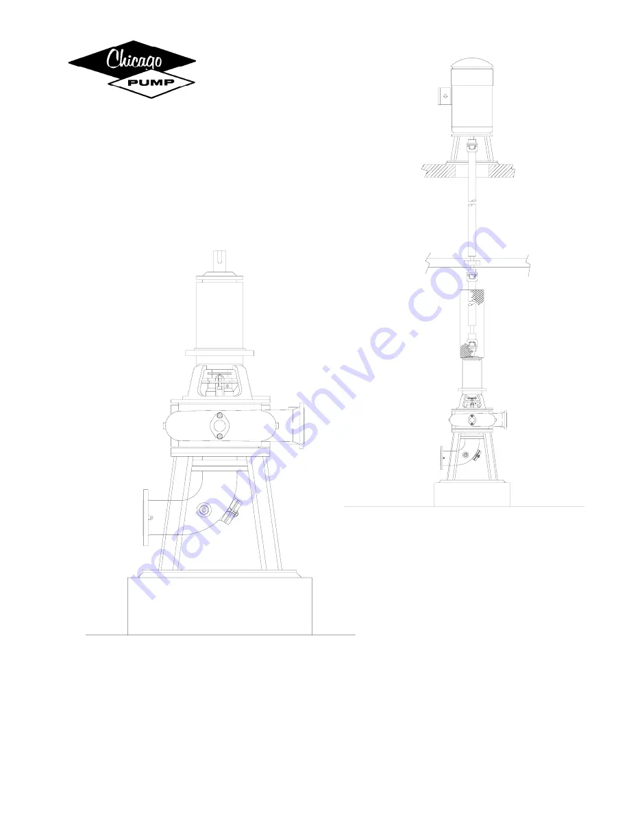
Type VOS, VPM and HBB Non-Clog Pumps
Frames: 64154A Thru 1412226, OS8-4A, OSC10-4A, LS8-4A
SERVICE INSTRUCTIONS MANUAL
Page 1: ...Instruction 2111 801C 01 04 1 CHICAGO PUMPCOMPANY Type VOS VPM and HBB Non Clog Pumps Frames 64154A Thru 1412226 OS8 4A OSC10 4A LS8 4A SERVICE INSTRUCTIONS MANUAL ...
Page 2: ...rting the Unit 8 Maintenance 8 Periodic Inspection 8 Shutting Down 9 Locating Trouble Pump Failure 9 No Water Delivered 9 Fuse Check 9 Repairs If Cleaning is required 10 Disassembly Procedure 10 To Remove Motor 10 Packing Disassembly 10 If Unit Equipped with Mechanical Seal 11 Shaft Sleeve Disassembly 11 Removal of Radial Bearing 11 Removal of Thrust Bearing 11 Reassembly Procedures 11 Bearing Hou...
Page 3: ... to move within the sleeve for aligning with the holes in the pump base The bolts are fastened to a template form usually made of wood and spaced to conform accurately with the pedestal anchor bolt holes The form is carefully located so that the pump will stand exactly in its specified position as to elevation shaft plumb and suction discharge pipe connections then the concrete is poured Before fi...
Page 4: ...swing check valve and a gate valve near the pump NOTE It is common practice where horizontal space does not permit to mount swing check valve in a vertical position 6 On vertical units install a drain pipe from the connection at packing box drip pocket to the sump line To be readily cleanable include a union in the line near the pump also tees with plugs should be used rather than elbows TO INSTAL...
Page 5: ...al currents available at the pump location Since motors may be direct current or single or three phase alternating current they may vary considerably according to the system of winding employed and are specific as to current requirements a discussion of controls covering all types would be lengthy and is therefore not attempted WIRING Connect the electric service to the controls and make inter con...
Page 6: ...is advisable to consult a lubrication engineer to determine the proper lubricant to use If this is not practical write to CHICAGO PUMP Company stating your conditions and we will procure the information for you PACKING BOXES PACKING AND PACKING SEALS 1 Packing Boxes The pumps employ gland adjusted packing boxes for sealing around the shafts Packing boxes are packed before shipment Packing material...
Page 7: ...orrosion by the liquid being pumped The faces have a minute running clearance and normally run on a very thin film of liquid The sealing liquid preferably clear water is injected into the seal box cartridge through a tapped connection at a pressure higher than that which would exist in the box thereby isolating the sealing faces from the liquid being pumped If sufficient sealing pressure is not ma...
Page 8: ...d line shafting see that incorrect installation has not resulted in its vibrating or whip ping 5 See that there is the desired water leakage from stuffing box refer to paragraph under Maintenance for details 6 See that bearings 8 11 do not overheat due either to over or under lubrication 7 Observe operation of pump closely for the first day and at regular intervals for two weeks A new machine is f...
Page 9: ...y bearings are not worn dry or jammed by corrosion that the shaft is properly aligned and that packing glands 16 are not too tightly or unevenly adjusted 3 See that switch contacts are not corroded shorted or terminal connections broken anywhere in the circuit 4 See if the automatic float control mechanism is functioning 5 See if motor is shorted or burnt or if brushes when present are stuck or wo...
Page 10: ... BEARING FRAME DISASSEMBLY 2 Remove cap screws and washers 19 Using a pry bar break the joint between casing cover 23 and volute 28 at gasket 24 Lift complete upper assembly including impeller 27 from volute 28 Place entire assembly on blocks with shaft horizontal and with impeller and pump half of coupling overhanging Remove coupling half by removing set screw s not shown 3 Inspect suction wear r...
Page 11: ... the section plate 62 to the pump support 39 when furnished Screws 37 secure the suction elbow 93 to the suction plate 62 The volute Handhole cover 51 is secured with screws 56 and the suction elbow Handhole cover is secured with screws 34 REASSEMBLY PROCEDURES When assembling and reassembling pumps CHICAGO PUMP strongly urges replacing all parts subject to wear as listed on parts list on page 10 ...
Page 12: ... and seal ring 32 intact 11 Place O ring 101 onto pump shaft 1 Install shaft sleeve 30 over shaft 1 Insert and tighten setscrew 98 Place gasket 124 on casing cover 23 and install assembled stuffing box onto shaft Secure to casing cover 23 with nuts 125 making sure that casing cover and stuffing box are properly lined up 12 Place bearing frame assembly horizontal on blocks or bench Go directly to i...
Page 13: ...eller 27 just touches suction plate 62 or impeller wear ring 54 just touches suction wear ring 80 Measures gap for shims 133 and add 1 32 Loosen cap screws 6 and evenly tighten adjusting screw 57 until desired shimming gap is obtained Install appropriate amount of shims 133 and tighten screws 6 Check that shaft turns freely Gland nuts can be tightened down a bit more securely but final gland adjus...
Page 14: ...will be supplied and must be strictly adhered to If questions arise as to the type of coupling supplied with the unit contact your CHICAGO PUMP representative The maximum parallel offset for factory standard couplings is 015 and the maximum angular offset is one 1 degree between pump shaft and motor shaft Alignment is checked with the flexible sleeve removed Using a straightedge and feeler gauges ...
Page 15: ...ction Plate XXX 39 Pump Support 40 Pipe Plug 43 Motor Support 47 Coupling Key 49 Cap Screw Nut Washer Motor Support to Bearing Housing 51 Volute Handhole Cover 52 Gasket Volute Handhole Cover XX 54 Impeller Wear Ring XXX XXX 55 Flat Head Machine Screws Impeller Wear Ring 5 6 XXX XX X Not Shown 56 Cap Screw Washer Volute Handhole Cover 57 Adjusting Screw 62 Suction Plate 63 Cap Screw Washer Suction...
Page 16: ...Instruction 2111 801C 01 04 16 CROSS SECTION DRAWINGS ...