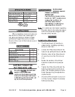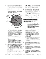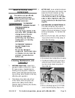
Page 13
For technical questions, please call 1-800-444-3353.
SKU 98107
installing the auxiliary Handle
tO preVent
seriOus injurY:
do not operate this tool with
one hand only or without the
auxiliary Handle properly
installed.
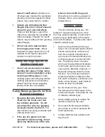
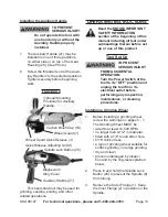
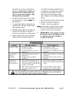
The Auxiliary Handle (27) may be
7.
installed in one of three positions,
on either side or on top of the Gear
Housing (28).
(See Photo.)
Screw the threaded end of the Auxil-
8.
iary Handle into the selected position.
Tighten securely before beginning
work.
Functions
Auxiliary Handle (27)
Optional Mounting
Positions for Auxiliary
Handle
Carbon Brush Cap (53)
Wheel Guard (7)
Wheel Guard Quick Release (3)
Spindle Lock Button (26)
Quick Release Adjusting Nut (8)
Magnesium
Alloy Cover
This hand-held tool may be used for
grinding, sanding, scaling, and other
related operations.
Operating instructiOns
read the entire iMpOrtant
saFetY inFOrMatiOn
section at the beginning of this
manual including all text under
subheadings therein before set
up or use of this product.
tool set up
tO preVent
seriOus injurY
FrOM accidental
OperatiOn:
turn the power switch of the
tool to its “OFF” position and
unplug the tool from its
electrical outlet before
performing any inspection,
maintenance, or cleaning
procedures.
installing a grinding wheel
Before installing a grinding wheel,
1.
review the warnings on pages 5 - 7.
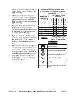
The Grinding Wheel MUST be:
rated to at least 10,500 RPM.
•
no larger than 4-1/2” in diameter.
•
fitted with a 7/8” round arbor hole.
•
5/16” thick or less.
•
a type of grinding wheel suitable for
•
surface grinding, not edge grinding.
dry and clean.
•
proven undamaged by inspec-
•
tion and by the ring-test explained
below.
Press in and hold the Spindle Lock
2.
Button (26) to prevent the Spindle (9)
from turning.
Remove the Outer Flange (1). Keep
3.
the Inner Flange (2) in position on the
Spindle.


