Chicago Electric 97743 Set Up And Operating Instructions Manual Download Page 13

Page 13

SKU 97743

For technical questions, please call 1-800-444-3353.
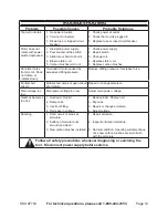
MAinTEnAncE And 

SERVicing

Procedures not specifically 

explained in this manual 

must be performed only by a 

qualified technician.


TO pREVEnT 

SERiOuS injuRY 

FROM AccidEnTAl 

OpERATiOn: 

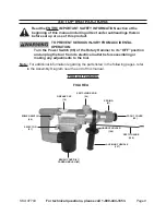
Turn the power Switch (96) of 

the Rotary Hammer to its 

“OFF” position and unplug 

the tool from its electrical 

outlet before performing any 

inspection, maintenance, or 

cleaning procedures.
TO pREVEnT SERiOuS 

injuRY FROM TOOl 

FAiluRE: 

do not use damaged 

equipment.  if abnormal noise 

or vibration occurs, have the 

problem corrected before 

further use.

BEFORE EAcH uSE:

1. 

  Inspect 

the general condition of the Rotary 

Hammer.  Check for loose screws, 

misalignment or binding of moving 

parts, cracked or broken parts, 

damaged electrical wiring, and any 

other condition that may affect its 

safe operation.

AFTER EVERY 50 HOuRS OF uSE:  

2. 

Use the Spanner Wrench provided to 

unscrew the Grease Cap (18).  Add 

the Grease provided.  Then, replace 

and tighten the Grease Cap.  

nOTE:  

The Rotary Hammer is pre-greased 

from the manufacturer.  Lubrication is 

only needed beginning after about 50 

hours of use.  

(See Figure A.)

TO cHAngE OR clEAn THE 

3. 

cARBOn BRuSHES:

  It may 

become necessary at sometime 

to replace or clean the two 

Carbon Brushes (82) when Motor 

performance decreases, or stops 

working completely.  The Carbon 

Brushes are located on each side of 

the Motor Housing (78).  To change 

or clean the Carbon Brushes:

 Remove the two Brush Covers 

• 

(81).  Then remove the Carbon 

Brushes.
If the Carbon Brushes (82) are worn 

• 

down more than 1/2, replace both 

Brushes.
If the Carbon Brushes (82) are 

• 

only dirty, they may be cleaned by 

rubbing them with a pencil eraser.
When installing the Carbon Brushes 

• 

(82), make sure the carbon portion 

of the Brushes contact the Motor 

Armature, and that the springs face 

away from the Armature.  Also, 

make sure the springs operate 

freely.  After replacing or cleaning, 

replace the two Brush Covers (81).
NOTE:  New Carbon Brushes (82) 

• 

tend to arc or spark when first used 

until they wear and conform to the 

Armature.  

(See Figure A.)


AFTER uSE: 

4. 

 Clean external 

surfaces of the tool with a clean cloth.

WARning!  if the power cord 

5. 

(112) of this Rotary Hammer is 

damaged, it must be replaced only 

by a qualified service technician.

Summary of Contents for 97743

Page 1: ...ssion Oaks Blvd Camarillo CA 93011 Visit our website at http www harborfreight com Read this material before using this product Failure to do so can result in serious injury Save this manual Copyright 2008 by Harbor Freight Tools All rights reserved No portion of this manual or any artwork contained herein may be reproduced in any shape or form without the express written consent of Harbor Freight...

Page 2: ...ymbol indicates a hazardous situation which if not avoided could result in minor or moderate injury NOTICE is used to address practices not related to personal injury CAUTION without the safety alert symbol is used to address practices not related to personal injury General Power Tool Safety Warnings WARNING Read all safety warnings and instructions Failure to follow the warnings and instructions ...

Page 3: ...sonal protective equip b ment Always wear eye protection Safety equipment such as dust mask non skid safety shoes hard hat or hearing protection used for appropri ate conditions will reduce personal injuries Prevent unintentional starting c Ensure the switch is in the off po sition before connecting to power source and or battery pack pick ing up or carrying the tool Carry ing power tools with you...

Page 4: ... less likely to bind and are easier to control Use the power tool accessories g and tool bits etc in accordance with these instructions taking into account the working conditions and the work to be performed Use of the power tool for operations different from those intended could result in a hazardous situation Service 5 Have your power tool serviced by a a qualified repair person using only ident...

Page 5: ...e or pacemaker failure In addition people with pacemakers should Avoid operating alone Do not use with power switch locked on Properly maintain and inspect to avoid electrical shock Any power cord must be properly grounded Ground Fault Circuit Interrupter GFCI should also be implemented it prevents sustained electrical shock Some dust created by power 15 sanding sawing grinding drilling and other ...

Page 6: ...ncreasing the risk of vibration related injury Wear suitable gloves to reduce the 3 vibration effects on the user Use tools with the lowest vibration 4 when there is a choice between different processes Include vibration free periods each 5 day of work Grip tool as lightly as possible while 6 still keeping safe control of it Let the tool do the work To reduce vibration maintain the tool 7 as expla...

Page 7: ...A requirements and complies with the applicable standards of Underwriters Laboratories Inc the Canadian Standard Association and the National Electrical Code See Outlets for 2 Prong Plug Double insulated tools may be used 2 in either of the 120 volt outlets shown in the preceding illustration See Outlets for 2 Prong Plug Extension Cords Grounded tools require a three wire 1 extension cord Double I...

Page 8: ...line voltage drop to five volts at 150 of the rated amperes Symbology Double Insulated Canadian Standards Association Underwriters Laboratories Inc V Volts Alternating Current A Amperes n0 xxxx min No Load Revolutions per Minute RPM Specifications Electrical Requirements 120 V 60 Hz 620 W 2 Prong Polarized Power Plug Speed n0 750 min Blows Per Minute 2920 BPM Capacity 1 Chuck Type SDS Rotation Clo...

Page 9: ...n Turn the Power Switch 96 of the Rotary Hammer to its OFF position and unplug the tool from its electrical outlet before assembling or making any adjustments to the tool Note For additional information regarding the parts listed in the following pages refer to the Assembly Diagram near the end of this manual Product Features POWER SWITCH 96 SWITCHING KNOB 24 SPRING 41 DEPTH GAUGE 106 AUXILIARY HA...

Page 10: ...ip of the Drill Bit to the tip of the Depth Gauge For example for a 2 deep hole measure 2 back from the tip of the Drill Bit Then position the front tip of the Depth Gauge at that spot See Figure A After the Depth Gauge 106 is 5 placed in the desired position turn the Auxiliary Handle 107 clockwise until tight The Depth Gauge should be securely in position and should not move See Figure A Changing...

Page 11: ... exposing the Power Cord to possible damage The Power Cord must reach the work area with enough extra length to allow free movement while working Secure loose workpieces using a vise 3 or clamps not included to prevent movement while working There must not be hazardous 4 objects such as utility lines or foreign objects nearby that will present a hazard while working Operating Instructions Read the...

Page 12: ...witch 96 is 2 in its OFF position Then plug the Power Cord 112 into the nearest 110 volt grounded electrical outlet See Figure A When ready to use the Rotary 3 Hammer squeeze the Power Switch 96 and allow the tool to run without load for about one minute This allows the tool s parts to become properly lubricated Check to see if the running tool sounds normal Once the tool has been warmed up it is ...

Page 13: ...is pre greased from the manufacturer Lubrication is only needed beginning after about 50 hours of use See Figure A TO CHANGE OR CLEAN THE 3 CARBON BRUSHES It may become necessary at sometime to replace or clean the two Carbon Brushes 82 when Motor performance decreases or stops working completely The Carbon Brushes are located on each side of the Motor Housing 78 To change or clean the Carbon Brus...

Page 14: ... or rotates slowly Overload of motor caused by excessive drilling pressure Reduce drilling pressure Decrease force Partial short circuit Partial short circuit or open circuit at armature Repair or change armature Main voltage too low Main power voltage too low Adjust main power voltage Gearbox becomes too hot Overload Dull bit 1 Damp coils 2 Incorrect fitting 3 Decrease in voltage 4 Reduce load Sh...

Page 15: ...liary 1 28 Handle Seat 2 29 Handle Bracket 1 30 Screw M5x25 4 31 Spring 4 32 Cylinder Case 1 33 Cylinder Cap 1 34 Oil Seal 1 Part Description Qty 35 Washer 1 36 Bearing 1 37 Distance Ring 1 38 Distance Cover 1 39 Front Cover 1 40 O Ring 1 41 Spring 1 42 Steel Column 2 43 Retainer Sleeve 1 44 O Ring 2 45 O Ring 2 46 Second Hammer 1 47 Spring 1 48 Name Plate 1 49 Oil Seal Ring 1 50 Gear Bearing 1 51...

Page 16: ... replacement parts thereto or arising out of his or her installation of replacement parts thereto Part Description Qty 67 Washer 1 68 Spring 1 69 Clutch Shaft 1 70 Center Cover 1 71 Bearing 1 72 Armature 1 73 Fan Guide 1 74 Field Screw 2 75 Washer 2 77 Bearing 1 78 Housing 1 79 Washer 4 80 Screw M5x50 4 81 Brush Cover 2 82 Carbon Brush 2 83 Brush Holder 2 84 Tapping Screw 2 85 Back Cover 1 86 Fixe...

Page 17: ... 8 104 105 106 107 108 19 18 16 111 110 109 20 11 23 30 28 29 26 25 22 21 24 33 32 31 34 114 38 37 36 35 39 40 42 41 44 43 46 45 47 116 58 59 53 52 48 49 50 51 57 55 54 55 56 54 60 31 64 63 61 62 65 69 68 66 67 70 77 75 74 73 72 71 78 80 79 81 84 83 82 87 86 85 88 89 91 115 90 94 93 92 96 97 98 99 112 103 101 102 REV 09e ...

Page 18: ... in lieu of all other warranties express or implied including the warranties of merchantability and fitness To take advantage of this warranty the product or part must be returned to us with transportation charges prepaid Proof of purchase date and an explanation of the complaint must accompany the merchandise If our inspection verifies the defect we will either repair or replace the product at ou...

Reviews: