background image

Page 7

For technical questions, please call 1-800-444-3353.

SKU 68394

Operating Instructions

  Read the ENTIRE IMPORTANT SAFETY 

INFORMATION section at the beginning 

of this manual including all text 

under subheadings therein before 

set up or use of this product.

Tool Set Up


TO PREVENT INJURY FROM 

ACCIDENTAL OPERATION: 

Release the Trigger and disconnect Power Adapter 

before adjusting tool or installing accessories.

Charging Battery

1.  Insert the Adapter cord plug into the 

back of the Screwdriver’s housing.

2.  Plug the Adapter module into an electrical 

outlet. The red Charging Indicator will 

light.  Charge up to 5-7 hours.

3.  Remove the Adapter from the electrical outlet.  The red 

Charging indicator will turn off. 


CAUTION! 

Do not overcharge the Battery.  Do 

not charger for more than 7 hours continuously.  

The Adapter should not be left connected after 

charging is complete during operation.

General Operating Instructions


TO PREVENT INJURY FROM 

ACCIDENTAL OPERATION: 

Release the Trigger and disconnect Adapter 

prior to making any adjustments to the tool.


1.  Disconnect the Power Adapter before operation.

The Screwdriver is designed to accept a 1/4” 

standard hex driver. Do not use larger drivers as 

damage to the gears and/or motor may result.

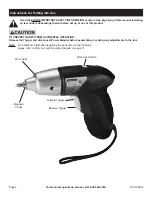
2.  Snap the desired hex driver into the Magnetic Chuck.

3.  If light is needed while driving screws, turn on 

the Work Light using the Work Light Switch.  

NOTE:

 The Work Light will activate once the 

Forward or Reverse Trigger is pressed.

4.  Engage the Screwdriver bit over the item being turned. 

The bit size must match the size of the screw.

5.  Squeeze and hold down the top Forward Trigger to 

start clockwise rotation.  For reverse (counterclockwise) 

rotation, squeeze the bottom Reverse Trigger. 

6.  When finished using the Screwdriver, release the 

Forward / Reverse Trigger to turn off the tool. 

7.  Clean then store the Screwdriver indoors 

and out of children’s reach.

Maintenance and Servicing

  Procedures not specifically explained 

in this manual must be performed 

only by a qualified technician.


TO PREVENT INJURY FROM 

ACCIDENTAL OPERATION: 

Release the Trigger and disconnect 

Adapter before performing any inspection, 

maintenance, or cleaning procedures.

TO PREVENT INJURY FROM TOOL FAILURE: 

Do not use damaged equipment.  If abnormal 

noise or vibration occurs, have the problem 

corrected before further use.

Cleaning, Maintenance, 

and Lubrication

1. 

BEFORE EACH USE,

 inspect the general condition 

of the tool.  Check for loose hardware, misalignment 

or binding of moving parts, cracked or broken 

parts, damaged electrical wiring, and any other 

condition that may affect its safe operation.

2. 

AFTER USE,

 wipe external surfaces of the tool with 

clean cloth. 


NOTE:

 INTERNAL 

Ni-Cd BATTERY MUST BE 

REMOVED AND DISPOSED OF PROPERLY.  Do 

not short, incinerate or open internal battery.

3.  When storing, always store in clean, dry and 

safe location out of reach of children.

4. 

WARNING!  If the supply cord of this power 

tool’s adapter is damaged, it must be replaced 

only by a qualified service technician.

Summary of Contents for 68394

Page 1: ...oon as possible Visit our website at http www harborfreight com Copyright 2011 by Harbor Freight Tools All rights reserved No portion of this manual or any artwork contained herein may be reproduced in any shape or form without the express written consent of Harbor Freight Tools Diagrams within this manual may not be drawn proportionally Due to continuing improvements actual product may differ sli...

Page 2: ...ed could result in death or serious injury CAUTION used with the safety alert symbol indicates a hazardous situation which if not avoided could result in minor or moderate injury NOTICE is used to address practices not related to personal injury CAUTION without the safety alert symbol is used to address practices not related to personal injury General Power Tool Safety Warnings WARNING Read all sa...

Page 3: ...ore making any adjustments changing accessories or storing power tools Such preventive safety measures reduce the risk of starting the power tool accidentally d Store idle power tools out of the reach of children and do not allow persons unfamiliar with the power tool or these instructions to operate the power tool Power tools are dangerous in the hands of untrained users e Maintain power tools Ch...

Page 4: ...s or other reproductive harm Wash hands after handling California Health Safety Code 25249 5 et seq 11 The warnings precautions and instructions discussed in this instruction manual cannot cover all possible conditions and situations that may occur It must be understood by the operator that common sense and caution are factors which cannot be built into this product but must be supplied by the ope...

Page 5: ...ouble insulation system which satisfies OSHA requirements and complies with the applicable standards of Underwriters Laboratories Inc the Canadian Standard Association and the National Electrical Code 2 Double insulated tools may be used in either of the 120 volt outlets shown in the preceding illustration See Outlets for 2 Prong Plug Extension Cords Note Extension cords must not be used with this...

Page 6: ...ubheadings therein before set up or use of this product TO PREVENT INJURY FROM ACCIDENTAL OPERATION Release the Trigger and disconnect Power Adapter before assembling or making any adjustments to the tool Note For additional information regarding the parts listed in the following pages refer to Parts List and Assembly Diagram on page 11 Magnetic Chuck Work Light Switch Work Light Forward Trigger R...

Page 7: ...rk Light will activate once the Forward or Reverse Trigger is pressed 4 Engage the Screwdriver bit over the item being turned The bit size must match the size of the screw 5 Squeeze and hold down the top Forward Trigger to start clockwise rotation For reverse counterclockwise rotation squeeze the bottom Reverse Trigger 6 When finished using the Screwdriver release the Forward Reverse Trigger to tu...

Page 8: ...ND OR DISTRIBUTOR HAS PROVIDED THE PARTS LIST AND ASSEMBLY DIAGRAM IN THIS MANUAL AS A REFERENCE TOOL ONLY NEITHER THE MANUFACTURER OR DISTRIBUTOR MAKES ANY REPRESENTATION OR WARRANTY OF ANY KIND TO THE BUYER THAT HE OR SHE IS QUALIFIED TO MAKE ANY REPAIRS TO THE PRODUCT OR THAT HE OR SHE IS QUALIFIED TO REPLACE ANY PARTS OF THE PRODUCT IN FACT THE MANUFACTURER AND OR DISTRIBUTOR EXPRESSLY STATES ...

Page 9: ...1 23 24 25 26 27 28 29 30 31 32 Record Product s Serial Number Here Note If product has no serial number record month and year of purchase instead Note Some parts are listed and shown for illustration purposes only and are not available individually as replacement parts 33 34 Parts List and Assembly Diagram Assembly Diagram ...

Page 10: ...al damages so the above limitation of exclusion may not apply to you THIS WARRANTY IS EXPRESSLY IN LIEU OF ALL OTHER WARRANTIES EXPRESS OR IMPLIED INCLUDING THE WARRANTIES OF MERCHANTABILITY AND FITNESS To take advantage of this warranty the product or part must be returned to us with transportation charges prepaid Proof of purchase date and an explanation of the complaint must accompany the merch...

Reviews: