Chicago Electric 67560 Set Up, Operating, And Servicing Instructions Download Page 31

Page 31

for technical questions, please call 1-800-444-3353.

SKU 67561 


owner’s Warranty Responsibilities

As the engine owner, you are responsible for the performance 

• 

of the required maintenance listed in your Owner’s Manual. 

HFT  recommends  that  you  retain  all  receipts  covering 

maintenance on your engine, but HFT cannot deny warranty 

solely for the lack of receipts or for your failure to ensure the 

performance of all scheduled maintenance.
As the engine owner, you should, however, be aware that 

• 

HFT may deny you warranty coverage if your engine or a part 

has failed due to abuse, neglect, improper maintenance, or 

unapproved modifications.

You  are  responsible  for  shipping  your  engine  to  a  HFT 

• 

warranty station as soon as a problem exists.  Contact the 

HFT Customer Service department at the number below to 

make shipping arrangements.  The warranty repairs should 

be completed in a reasonable amount of time, not to exceed 

30 days.
If  you  have  any  questions  regarding  your  warranty  rights 

and responsibilities, you should contact the Harbor Freight Tools 

Customer Service Department at 1-800-444-3353.

harbor freight Tools Emission Control Defects 

Warranty provisions

length of Coverage

1. 

HFT warrants to a first retail purchaser and each subsequent 

purchaser that the engine is free from defects in materials 

and workmanship that cause the failure of warranted parts 

for a period of two (2) years after the date of delivery to the 

first retail purchaser.

no Charge Repair or Replacement

2. 

Repair or replacement of any warranted part will be performed 

at no charge to the owner if the work is performed through a 

warranty station authorized by HFT.  For emissions warranty 

service, contact the HFT Customer Service Department at 

1-800-444-3353.

Consequential Damages Coverage

3. 

Coverage under this warranty shall also extend to the failure 

of  any  engine  components  caused  by  the  failure  of  any 

warranted part while it is still covered under this warranty.

Coverage Exclusions

4. 

Warranty  claims  shall  be  filed  in  accordance  with  the 

provisions of the HFT warranty policy explained in the box 

at the top of the previous page.  HFT shall not be liable for 

any  loss  of  use  of  the  engine,  for  any  alternative  usage, 

for any damage to goods, loss of time, or inconvenience.  

Warranty coverage shall also be excluded for any part which 

fails,  malfunctions,  or  is  damaged  due  to  failure  to  follow 

the maintenance and operating instructions set forth in the 

Owner’s Manual including, but not limited to:

Use of parts which are not authorized by HFT

a) 

Improper installation, adjustment or repair of the engine 

b) 

or  of  any  warranted  part  unless  performed  by  an 

authorized warranty center
Failure to follow recommendations on fuel use contained 

c) 

in the Owner’s Manual
Improper or inadequate maintenance of any warranted 

d) 

parts
Repairs performed outside of the authorized warranty 

e) 

service dealers
Alterations by changing, adding to or removing parts 

f) 

from the engine.

service and Maintenance

5. 

Component parts which are not scheduled for replacement 

as required maintenance or are scheduled only for regular 

inspection to the effect of “repair or replace as necessary” 

are warranted for the warranty period. Any warranted part 

which is scheduled for replacement as required maintenance 

is warranted for the period of time up to the first scheduled 

replacement  point  for  that  part.   Any  replacement  part, 

provided it is equivalent in durability and performance, may 

be  used  in  performance  of  maintenance  or  repairs.   The 

owner is responsible for commissioning a qualified technician/

mechanic to perform all required maintenance, as outlined 

in the Inspection, Cleaning, and Maintenance section in this 

manual.

Warranted parts

6. 

Fuel Metering System

1) 

Carburetor and its internal parts.

i) 

Fuel pump (if so equipped).

ii) 

Cold start enrichment system.

iii) 
Air Induction System

2) 

Intake pipe/manifold.

i) 

Air cleaner.

ii) 
Ignition System

3) 

Spark plug.

i) 

Magneto ignition system.

ii) 
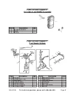
Catalyst System (if so equipped)

4) 

Exhaust pipe stud.

i) 

Muffler.

ii) 

Catalytic converter (if so equipped).

iii) 
Miscellaneous Items Used in Above Systems

5) 

Vacuum,  temperature  and  time  sensitive  valves 

i) 

and switches.
Hoses, belts, connectors, and assemblies.

ii) 

Summary of Contents for 67560

Page 1: ...any shape or form without the express written consent of Harbor Freight Tools Diagrams within this manual may not be drawn proportionally Due to continuing improvements actual product may differ slightly from the product described herein Tools required for assembly and service may not be included For technical questions or replacement parts please call 1 800 444 3353 Using an engine indoors CAN KI...

Page 2: ... 16 After Initial 20 Operation Hour Period 16 Every 25 Operation Hours Thereafter 16 Every 50 Operation Hours 16 Every 100 Operation Hours 16 Every 300 Operation Hours 16 Storage 16 Engine Troubleshooting 18 Equipment Troubleshooting 20 Main Parts List 21 Main Assembly Diagram 22 Parts List and Diagram A Crankcase Assembly 23 Parts List and Diagram B Cylinder Head Assembly 24 Parts List and Diagra...

Page 3: ...t in death or serious injury CAUTION used with the safety alert symbol indicates a hazardous situation which if not avoided could result in minor or moderate injury NOTICE is used to address practices not related to personal injury CAUTION without the safety alert symbol is used to address practices not related to personal injury WARNING Read all instructions Failure to follow all instructions lis...

Page 4: ...g use People with pacemakers should 5 consult their physician s before use Electromagnetic fields in close proximity to a heart pacemaker could cause pacemaker interference or pacemaker failure Caution is necessary when near the engine s magneto or recoil starter Use only accessories that are 6 recommended by Harbor Freight Tools for your model Accessories that may be suitable for one piece of equ...

Page 5: ...aintained equipment Use the correct equipment for the 21 application Do not modify the equipment and do not use the equipment for a purpose for which it is not intended CAUTION 22 This generator is not intended to power sensitive electronic equipment without the addition of an appropriate line conditioner and surge protector both not included Sensitive electronic equipment should be operated on ap...

Page 6: ...all safety guards in place and in 2 proper working order Safety guards include muffler air cleaner mechanical guards and heat shields among other guards Do not alter or adjust any part of the 3 equipment or its engine that is sealed by the manufacturer or distributor Only a qualified service technician may adjust parts that may increase or decrease governed engine speed Wear ANSI approved safety g...

Page 7: ...A If you are using one extension cord 5 for more than one tool add the nameplate amperes and use the sum to determine the required minimum cord size See Table A If you are using an extension cord 6 outdoors make sure it is marked with the suffix W A W in Canada to indicate it is acceptable for outdoor use Make sure the extension cord is 7 properly wired and in good electrical condition Always repl...

Page 8: ...refer to the last pages of this manual At high altitudes the engine s carburetor governor if so equipped and any other parts that control the fuel air ratio will need to be adjusted by a qualified technician to allow efficient high altitude use and to prevent damage to the engine and any other devices used with this product Functions This unit can power items such as the following ITEM RUNNING WAT...

Page 9: ...g for up to 20A Figure 1 Plug for up to 15A 120V Duplex Receptacle for 15A or 20A plugs Engine Power Switch Power Indicator Light AC Circuit Breaker Switch 120 V Duplex Receptacle 120 V Twist Lock Receptacle AC Reset Switch DC Circuit Breaker Switch 10 Amps Ground Wire Connection 12 VDC Outlet MAIN BREAKER 20A RESET 120V AC OUTLETS ONLY ...

Page 10: ...e with low or no engine oil Running the engine with no or low engine oil WILL permanently damage the engine Check the oil level with the engine stopped and in a level position Wipe dipstick exterior with a clean 1 cloth Remove the dipstick and wipe it off with a clean rag Pour engine oil into the oil fill hole until the level of oil is even with the bottom edge of the oil fill hole if you cannot s...

Page 11: ...replace the Fuel Tank Cap 6 Start Procedure Before starting the engine Inspect the equipment and a engine Fill the engine with the b proper amount and type of fuel and oil Read the Equipment c Operation section that follows Unplug loads from the Generator and 1 make sure the AC Circuit Breaker Switch is in the OFF position before starting to prevent permanent generator damage Turn the engine fuel ...

Page 12: ... 1 grounded to avoid electrical shocks Connect a 10 gauge or larger insulated copper wire to the Ground Wire Connection on the Control Panel Connect this wire to a suitable external ground such as a copper stake in the ground Don t overload the generator The 2 total wattage used by the appliances should be less than the output rating of the generator If you put too many appliances on the generator...

Page 13: ...t all loads from the 8 generator before shutting off To prevent accidents turn off the engine and disconnect its spark plug wire after use Wait for the engine to cool clean external parts with clean cloth then store the equipment out of children s reach according to the Storage instructions in this manual Control Panel Features Engine Power Switch must be in ON 1 position for engine to start and r...

Page 14: ...ss smoking occurs have the problem corrected before further use Maintenance Procedures Many maintenance procedures including those not detailed in this manual will need to be performed by a qualified technician for safety If you have any doubts about your ability to safely service the equipment or engine have a qualified technician service the equipment instead Note Warranty is void if proper main...

Page 15: ... plug wrench remove 2 the spark plug Inspect the spark plug 3 If the electrode is oily clean it using a clean dry rag If the electrode has deposits on it polish it using emery paper If the white insulator is cracked or chipped the spark plug needs to be replaced When installing a new spark 4 plug adjust the plug s gap to the specification on the Technical specification chart Do not pry against the...

Page 16: ... 50 and 100 operation hours should be performed at least yearly Every 300 Operation Hours Clean fuel tank and carburetor a Clean carbon build up from b combustion chamber Check oil tube condition and replace c as needed Storage Wait for engine to cool then clean 1 engine with clean cloth When the equipment is to remain idle 2 for longer than 20 days prepare the engine for storage as follows Change...

Page 17: ...eated gasoline will deteriorate quickly Place a container below the carbure a tor bowl and drain the fuel from the fuel tank and carburetor bowl Discard the drained fuel properly as b per local ordinance Change to fresh fuel if untreated c gasoline has been sitting for a month if treated gasoline has been sitting beyond the fuel stabilizer s recommended time period or if the engine does not start ...

Page 18: ...lerances repair or replace as needed Check compression replace as 2 needed Check wear tolerances repair or 3 replace as needed Problem Engine does not start or does not run smoothly See chart below Symptom Possible Cause Possible Solution Engine is Pinging Excess wear of Piston Cylinder Wall or Rings Piston Pin or Piston Pin Hole Connecting Rod Wrist Pin Crankshaft Roller Bearing Check wear replac...

Page 19: ... spark plug wire 4 replace as needed Check coil continuity and output 5 Mechanical problem Engine Piston Piston Rod Valve 1 or Crankshaft may be damaged Generator Shaft may be seized 2 Have serviced by a qualified 1 technician Disconnect engine and attempt to 2 rotate generator shaft by hand Repair or replace as needed Problem Engine runs excessively hot See chart below Problem Possible Cause Poss...

Page 20: ...outlets AC Breaker switch in the OFF 1 position AC circuits overloaded 2 Reset the Breaker Switch to the ON 1 position Disconnect some appliances to 2 reduce the load No power at the 12 VDC outlet DC Breaker Switch open Disconnect the 12 Volt appliance then press the 12 VDC breaker switch IN Reconnect the 12 V accessory Follow all safety precautions whenever diagnosing or servicing the equipment o...

Page 21: ... Screw M8X25 4 41 Flange Screw M8 4 42 Flange Screw M6X45 2 43 Spring washer 6 2 44 Plate washer 6 2 45 Plate washer 8 4 46 Spring washer 8 4 Part Description Qty 47 Flange Screw M8X25 4 48 Washer 8 1 49 Spring washer 8 1 50 Flange Screw 5 16 210 24UNC 1 51 Flange Screw M6X130 4 52 Spring washer 6 4 53 Toothed Washer 5 1 54 Plate washer 5 1 55 Spring washer 5 1 56 Flange Screw M5X16 1 57 Full scre...

Page 22: ...Page 22 For technical questions please call 1 800 444 3353 SKU 67561 Ť ᆦ Ţ Ť Ţ ᆦ ᆦ Ť ᆦ ᆦ ᆦ Ť ᆦ 72 Ť ᆦ ᆦ Ť ᆦ ᆦ Main Assembly Diagram ...

Page 23: ... Dipstick with Seal 2 a 12 Crankcase Cover 1 a 13 Crankcase Gasket 1 a 14 Bearing 6205 2 a 15 Set Pin m 8 x 14 2 a 16 Bolt m8 x 33 5 6 NOTE Not all engine sub assembly components shown on the following pages are available as separate replacement parts They may be shown for informational purposes only NOTE All part numbers listed on the following pages have a letter suffix For example the Crankcase...

Page 24: ...et 1 b 4 Valve Rocker Assembly 1 b 5 Push Guide 1 b 6 Cap 1 b 7 Exhaust Spring Seat 1 b 8 Intake Spring Seat 1 b 9 Valve Spring 2 b 10 Bolt m 8 x 60 4 b 11 Stud AM 8 x 34 2 b 12 Cylinder Head Assembly 1 Part Description Qty b 13 Cylinder Head Gasket 1 b 14 Set Pin 2 b 15 Exhaust Valve 1 b 16 Intake Valve 1 b 17 Tappet 2 b 18 Pusher 2 b 19 Stud AM 6 x 112 2 b 20 Lead Wind Cover 1 b 21 Oil Pipe Seal...

Page 25: ...ting Rod Camshaft and Flywheel Assemblies Part Description Qty c 1 Piston Ring Set 1 c 2 Piston Ring Circlip 2 c 3 Piston 1 c 4 Piston Pin 1 c 5 Connecting Rod Assembly 1 c 6 Crankshaft Assembly 1 Part Description Qty c 7 Camshaft Assembly 1 c 8 Flywheel 1 c 9 Flywheel Fan 1 c 10 Starting Flange 1 c 11 Nut m 14 x 1 5 1 ...

Page 26: ... Ignition Coil Assembly Part Description Qty d 1 Engine Switch 1 d 2 Fan Hood 2 d 3 Bolt m 6 x 12 5 d 4 Bolt m 6 x 8 4 d 5 Recoil Starter Assembly 1 d 6 Complete Shroud 1 Part Description Qty d 7 Diode 1 d 8 Oil Sensor 1 d 9 Bolt m 6 x 14 2 d 10 Bolt m 6 x 22 2 d 11 Ignition Coil Assembly 1 d 12 Spark Plug F6TC 1 ...

Page 27: ...Duct 1 Parts List and Diagram F Fuel Supply System Part Description Qty f 1 Pipe Clamp 2 f 2 Fuel Pipe m 4 5 x 170 1 f 3 Intake Gasket 1 f 4 Connecting Block 1 f 5 Carburetor Gasket 1 f 6 Carburetor Assembly 1 f 7 Air Cleaner Gasket 1 Part Description Qty f 8 Regulator Assembly 1 f 9 Back Spring 1 f 10 Regulating Spring 1 f 11 Pulling Rod 1 f 12 Lock Bolt 1 f 13 Regulating Spring 1 f 14 Nut M6 1 ...

Page 28: ...x 28 1 g 3 Bolt m6 x 32 1 g 4 Crankcase 1 g 5 Charge Coil 1 Part Description Qty g 6 Bolt m6 x 35 2 g 7 Clamp Cord 1 g 8 Bolt m6 x 12 2 g 9 Flywheel 1 Record Product s Serial Number Here Note If product has no serial number record month and year of purchase instead Note Some parts are listed and shown for illustration purposes only and are not avail able individually as replacement parts ...

Page 29: ...Page 29 For technical questions please call 1 800 444 3353 SKU 67561 Wiring Diagram ...

Page 30: ...red products at our expense but if we determine there is no defect or that the defect resulted from causes not within the scope of our warranty then you must bear the cost of returning the product This warranty gives you specific legal rights and you may also have other rights which vary from state to state 3491 Mission Oaks Blvd PO Box 6009 Camarillo CA 93011 800 444 3353 Emission Control System ...

Page 31: ...be filed in accordance with the provisions of the HFT warranty policy explained in the box at the top of the previous page HFT shall not be liable for any loss of use of the engine for any alternative usage for any damage to goods loss of time or inconvenience Warranty coverage shall also be excluded for any part which fails malfunctions or is damaged due to failure to follow the maintenance and o...

Reviews: