background image

Page 7

For technical questions, please call 1-888-866-5797.

Item 62356 


SAFETY

Op

ERA

TION

M

AINTENAN

c

E

SETU

p

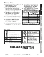
Extension cords

1. 

Grounded

 tools require a three wire extension cord.  

Double Insulated

 tools can use either 

a two or three wire extension cord.

2.  As the distance from the supply outlet increases, 

you must use a heavier gauge extension cord.  

Using extension cords with inadequately sized wire 

causes a serious drop in voltage, resulting in loss of 

power and possible tool damage.  

(See Table A.)

3.  The smaller the gauge number of the wire, the 

greater the capacity of the cord.  For example, 

a 14 gauge cord can carry a higher current 

than a 16 gauge cord.  

(See Table A.)

4.  When using more than one extension cord to make 

up the total length, make sure each cord contains at 

least the minimum wire size required.  

(See Table A.)

5.  If you are using one extension cord for more 

than one tool, add the nameplate


amperes 

and use the sum to determine the required 

minimum cord size.  

(See Table A.)

6.  If you are using an extension cord outdoors, make 

sure it is marked with the suffix “W-A” (“W” in 

Canada) to indicate it is acceptable for outdoor use.

7.  Make sure the extension cord is properly wired 

and in good electrical condition.  Always replace 

a damaged extension cord or have it repaired 

by a qualified electrician before using it.

8.  Protect the extension cords from sharp objects, 

excessive heat, and damp or wet areas.

TABLE A:  REcOMMENDED MINIMUM WIRE 

GAUGE FOR EXTENSION cORDS* (120/240 VOLT)

NAMEpLATE

AMpERES

(at full load)

EXTENSION cORD 

LENGTH

25´ 50´ 75´ 100´ 150´

0 – 2.0

18

18

18

18

16

2.1 – 3.4

18

18

18

16

14

3.5 – 5.0

18

18

16

14

12

5.1 – 7.0

18

16

14

12

12

7.1 – 12.0

18

14

12

10

-

12.1 – 16.0

14

12

10

-

-

16.1 – 20.0

12

10

-

-

-

* Based on limiting the line voltage drop to five volts at 

150% of the rated amperes.

Symbology

Double Insulated

Canadian Standards Association

Underwriters Laboratories, Inc.

VAc

Volts Alternating Current

A

Amperes

n0 xxxx/min.

No Load Revolutions per Minute (RPM)

WARNING marking concerning Risk 

of Eye Injury.  Wear ANSI-approved 

safety goggles with side shields.

Read the manual before 

set-up and/or use.

WARNING marking 

concerning Risk of Fire.  

Do not cover ventilation ducts.

Keep flammable objects away.

WARNING marking concerning 

Risk of Electric Shock.  

Properly connect power cord 

to appropriate outlet.

Summary of Contents for 62356

Page 1: ...mbly and service may not be included When unpacking make sure that the product is intact and undamaged If any parts are missing or broken please call 1 888 866 5797 as soon as possible Save This Manual Keep this manual for the safety warnings and precautions assembly operating inspection maintenance and cleaning procedures Write the product s serial number in the back of the manual near the assemb...

Page 2: ...ation which if not avoided could result in minor or moderate injury Addresses practices not related to personal injury IMPORTANT SAFETY INFORMATION General Power Tool Safety Warnings Read all safety warnings and instructions Failure to follow the warnings and instructions may result in electric shock fire and or serious injury Save all warnings and instructions for future reference The term power ...

Page 3: ... alcohol or medication A moment of inattention while operating power tools may result in serious personal injury 2 Use personal protective equipment Always wear eye protection Safety equipment such as dust mask non skid safety shoes hard hat or hearing protection used for appropriate conditions will reduce personal injuries 3 Prevent unintentional starting Ensure the Trigger is in the off position...

Page 4: ...s 1 Use auxiliary handle s if supplied with the tool Loss of control can cause personal injury 2 Hold power tools by insulated gripping surfaces when performing an operation where the cutting tool may contact hidden wiring or its own cord Contact with a live wire will make exposed metal parts of the tool live and shock the operator 3 Let bit cool before touching changing or adjusting it Bits heat ...

Page 5: ...he operator Vibration Safety This tool vibrates during use Repeated or long term exposure to vibration may cause temporary or permanent physical injury particularly to the hands arms and shoulders To reduce the risk of vibration related injury 1 Anyone using vibrating tools regularly or for an extended period should first be examined by a doctor and then have regular medical check ups to ensure me...

Page 6: ... to carry electricity away from the user reducing the risk of electric shock See 3 Prong Plug and Outlet 2 The grounding prong in the plug is connected through the green wire inside the cord to the grounding system in the tool The green wire in the cord must be the only wire connected to the tool s grounding system and must never be attached to an electrically live terminal See 3 Prong Plug and Ou...

Page 7: ...ked with the suffix W A W in Canada to indicate it is acceptable for outdoor use 7 Make sure the extension cord is properly wired and in good electrical condition Always replace a damaged extension cord or have it repaired by a qualified electrician before using it 8 Protect the extension cords from sharp objects excessive heat and damp or wet areas Table A RECOMMENDED MINIMUM WIRE GAUGE FOR EXTEN...

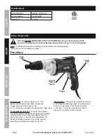
Page 8: ...k the Trigger in the ON position for continuous operation squeeze the Trigger and push in the Trigger Lock To turn off the tool squeeze and release the Trigger once Forward Reverse Switch To reverse the rotation turn off the Drywall Screwdriver and push the Forward Reverse Switch to the right when viewed from the back of the tool To position the Forward Reverse Switch for forward operation turn of...

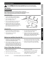
Page 9: ... the Bit straight out with pliers if it is difficult to remove 3 Push the new Bit into the Bit Holder until the shank of the Bit snaps in place 4 Replace the Depth Collar onto the Head Cover Align the ribs on the inside of the Depth Collar with the grooves on the outside of the Head Cover before snapping the Depth Collar in place Work piece and Work Area Set Up 1 Designate a work area that is clea...

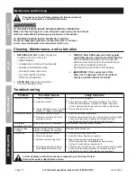
Page 10: ...tions Tool will not start 1 Cord not connected 2 No power at outlet 3 Internal damage or wear Carbon brushes or Trigger for example 1 Check that cord is plugged in 2 Check power at outlet If outlet is unpowered turn off tool and check circuit breaker If breaker is tripped make sure circuit is right capacity for tool and circuit has no other loads 3 Have technician service tool Tool operates slowly...

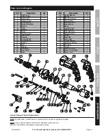
Page 11: ...using 1 5 Middle Cover 1 6 Break Wind Ring 1 7 Bearing 1 8 Rotor 1 9 Bearing 1 10 Stator 1 11 Carbon Brush 2 12 Rear Cover 1 13 Housing 1 14 Screw St4x52 2 15 Screw St4x16 5 16 Bearing 1 17 Gear 1 18 Washer 1 19 Steel Ball 1 20 Gear Shaft 1 21 Gear 1 Part Description Qty 22 Needle Bearing 3 23 Bearing 1 24 Bearing Retainer 1 25 Output Shaft 1 26 Retaining Ring 1 27 Impact Block 1 28 Spring 1 29 Lo...

Page 12: ...ctly or indirectly to misuse abuse negligence or accidents repairs or alterations outside our facilities criminal activity improper installation normal wear and tear or to lack of maintenance We shall in no event be liable for death injuries to persons or property or for incidental contingent special or consequential damages arising from the use of our product Some states do not allow the exclusio...

Reviews: