background image

PRODUCT SPECIFICATIONS


!"

#$%&#%'(")*

+-

& !/)56+7!/)

87)):!!

;<#%=><#%>?%

6

@%=DD)!6

!D

=/

SAVE THIS MANUAL

You will need this manual for the safety warnings and precautions, assembly,
operating, inspection, maintenance and cleaning procedures, parts list and as-
sembly diagram.  Keep your invoice with this manual.  Write the invoice number
on the inside of the front cover.  Keep this manual and invoice in a safe and dry
place for future reference.

GENERAL SAFETY RULES

WARNING!

READ AND UNDERSTAND ALL INSTRUCTIONS

Failure to follow  all instructions listed below may result in

electric shock, fire, and/or serious injury.

SAVE THESE INSTRUCTIONS

WORK AREA

1.

Keep your work area clean and well lit.

  Cluttered benches and dark areas

invite accidents.

2.

Do not operate power tools in explosive atmospheres, such as in the
presence of flammable liquids, gases, or dust.  

Power tools create sparks

which may ignite the dust or fumes.

SKU 03670

PAGE 2

E194601

3.

Keep bystanders, children, and visitors away while operating a power tool.

Distractions can cause you to lose control.  Protect others in the work area from
debris such as chips and sparks.  Provide barriers or shields as needed.

Summary of Contents for 3670

Page 1: ...at http www harborfreight com Copyright 2003 by Harbor Freight Tools All rights reserved No portion of this manual or any artwork contained herein may be reproduced in any shape or form without the express written consent of Harbor Freight Tools For technical questions please call 1 800 444 3353 3 8 VSR DRILL ...

Page 2: ...ONS Failure to follow all instructions listed below may result in electric shock fire and or serious injury SAVE THESE INSTRUCTIONS WORK AREA 1 Keep your work area clean and well lit Cluttered benches and dark areas invite accidents 2 Do not operate power tools in explosive atmospheres such as in the presence of flammable liquids gases or dust Power tools create sparks which may ignite the dust or...

Page 3: ...pes radiators ranges and refrigerators There is an increased risk of electric shock if your body is grounded 7 Do not expose power tools to rain or wet conditions Water entering a power tool will increase the risk of electric shock 8 Do not abuse the Power Cord Never use the Power Cord to carry the tools or pull the Plug from an outlet Keep the Power Cord away from heat oil sharp edges or moving p...

Page 4: ...rce the tool Use the correct tool for your application The correct tool will do the job better and safer at the rate for which it is designed 18 Do not use the power tool if the Power Switch does not turn it on or off Any tool that cannot be controlled with the Power Switch is dangerous and must be replaced 19 Disconnect the Power Cord Plug from the power source before making any adjustments chang...

Page 5: ... the Drill These carry important information If unreadable or missing contact Harbor Freight Tools for a replacement 3 Always wear safety impact eye goggles and heavy work gloves when using the Drill Using personal safety devices reduce the risk for injury Safety impact eye goggles and heavy work gloves are available from Harbor Freight Tools 4 Maintain a safe working environment Keep the work are...

Page 6: ...igned to filter out microscopic particles California Health Safety Code 25249 5 et seq 14 WARNING People with pacemakers should consult their physician s before using this product Operation of electrical equipment in close proximity to a heart pacemaker could cause interference or failure of the pacemaker SKU 03670 PAGE 6 GROUNDING WARNING Improperly connecting the grounding wire can result in the...

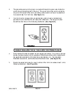
Page 7: ...es and ordinances The plug and outlet should look like those in the following illustration See Figure A FIGURE A SKU 03670 PAGE 7 FIGURE B DOUBLE INSULATED TOOLS TOOLS WITH TWO PRONG PLUGS 4 Tools marked Double Insulated do not require grounding They have a special double insulation system which satisfies OSHA requirements and complies with the applicable standards of Underwriters Laboratories Inc...

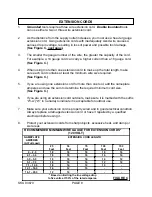
Page 8: ...re than one extension cord to make up the total length make sure each cord contains at least the minimum wire size required See Figure C 5 If you are using one extension cord for more than one tool add the nameplate amperes and use the sum to determine the required minimum cord size See Figure C EXTENSION CORDS 6 If you are using an extension cord outdoors make sure it is marked with the suffix W ...

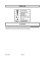
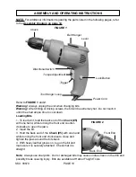
Page 9: ...ke sure all the parts shown on the Parts List on page 13 are included If any parts are missing or broken please call Harbor Freight Tools at the number shown on the cover of this manual as soon as possible Canadian Standards Association Underwriters Laboratories Inc No Load Revolutions per Minute RPM noxxxx min A V ...

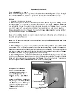
Page 10: ...ot touch it until it has had ample time to cool down 1 To load a bit hold the back end of the Chuck 5 with one hand while turning the front end counter clockwise to open the jaws 2 Insert the bit 3 Hold the back end of the Chuck 5 with one hand while turning the front end clockwise to close and tighten the jaws around the bit shank 4 With heavy leather gloves on tug on the bit and make sure it is ...

Page 11: ...f you need more or less torque use the Torque Adjustment on the Trigger Turning the Torque Adjustment screw toward the sign will add more torque See FIGURE 3 Note When drilling plastics or plastic coated chip board follow the same directions as stated in number 2 for wood Note If a bit becomes wedged into the workpiece change the Directional Switch to the reverse position 3 When drilling metal alw...

Page 12: ...arbon Brush Holder 15 on the side of the drill Take the Carbon Brush 14 out of the Carbon Brush Holder 15 If it is dirty use a pencil eraser to clean it If it is worn replace it and replace the Carbon Brush 14 If you replace one Carbon Brush you must replace them both Repeat the process with the Carbon Brush Holder 15 on the other side of the drill PLEASE READ THE FOLLOWING CAREFULLY THE MANUFACTU...

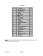
Page 13: ...12 Bearing 1 13 Armature 1 14 Carbon Brush 2 15 Carbon Brush Holder 2 16 Bearing 1 17 Stator 1 18 Clip 1 19 Self Tapping Screw 4 x 12 2 20 Cable Sheath 1 21 Power Cord and Plug 1 22 Switch Module 1 23 Limb 2 24 Outgoing Line 2 25 Limb 2 26 Right Motor Housing 1 27 Screw 4 x 16 2 28 Screw 4 x 20 6 NOTE Some parts are listed and shown for illustration purposes only and are not avail able individuall...

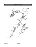
Page 14: ...SKU 03670 PAGE 14 ASSEMBLY DIAGRAM ...

Reviews: