


SKU 02954
Page 4
REV 04c
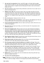
Special Warnings for This Tool
Inspect Cable thoroughly before use.
1.
Be sure Cable is attached properly and in
good condition. Do not use this tool if the Cable is frayed, kinked, or wrapped improp-
erly around the reel. Do not replace the Cable with another Cable of lesser strength.
Always leave at least three turns of Cable on the spool to insure that the Cable is able
to lift to the stated weight capacity.
Inspect the power Supply before use.
2.
Be sure the Power Cord and Control Handle
are in good condition before use. Avoid using this tool in damp or wet locations, or
exposing the components of this tool to moisture.
Route the power Cord away from other tools and equipment.
3.
Take care to prevent
damage to the Power Cord and the Control Handle Cord. If either become damaged,
have them repaired or replaced by a qualified technician before using this tool.
Stand back.
4.
Stay out of the direct line that the Cable is pulling. If it slips or breaks, it
will “whiplash” along this line. Never stand underneath a weight that is being lifted.
do not hold the Cable while using the tool.
5.
Your hand could get caught in moving
parts.
do not operate this tool alone.
6.
Use a spotter to help you see when it is safe to oper-
ate the tool.
Observe stated power limits.
7.
Do not attempt to lift more than 650 lb. when using a
single cable, or 1300 lb. when using a double cable.
Exercise caution when mounting this tool.
8.
This tool must be mounted to a jib boom
only. Mounting surface must be able to support the weight of this tool and the work
piece being lifted. Use the appropriate hardware when mounting tool.
People with pacemakers should consult their physician(s) before use. Electromag-
9.
netic fields in close proximity to heart pacemaker could cause pacemaker interference
or pacemaker failure.
Warning: The warnings, cautions, and instructions discussed in this instruction
10.
manual cannot cover all possible conditions and situations that may occur. It
must be understood by the operator that common sense and caution are factors
which cannot be built into this product, but must be supplied by the operator.
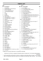
unpACKIng
When unpacking, check to make sure all parts listed on Page 7 are included. If any
parts are missing or broken, please call Harbor Freight Tools at the number on the cover of
this manual.


