7
24
Operating the Wireless Microphone System
To use the First wireless system, switch on the receiver module power supply switch of
WM1. Switch on the corresponding matching transmitter or handheld microphone ( please
refer to the operating instruction of the individual transmitter ). When RF signal is being
received by the receiver, the receiver RF signal indicator 1 will light up. Rotate the control
WM1 and MASTER volume control clockwise to increase the volume. When voice is spoken
into the microphone, amplified sound should be heard over the built-in speaker.
This instruction is for system which is equipped with two wireless receiver modules. To use
the Second wireless system, switch on the receiver module power supply switch WM2.
Switch on the corresponding matching transmitter or handheld microphone. When RF signal
is being received by the receiver, the receiver RF signal indicator 2 will light up. Rotate the
WM 2 control and MASTER volume control clockwise to increase the level. When voice is
spoken into the microphone, amplified sound should be heard over the built-in speaker.
Operating the Wired / Cable Microphone
To use the wired microphone, simply plug in the wired microphone connector into the XLR /
Phone jack combo connector . This unique connector accept either XLR or 1/4 Phone Jack
male connector. Rotate the MIC In volume control and MASTER Volume control clockwise
to increase the volume. When voice is spoken into the wired microphone, amplified sound
should be heard over the built-in or external speaker.
Both wired and wireless microphone could be used simultaneously as there is a built-in
mixer to mix both input signals.
When all the levels are set, simply use the MASTER volume control as main control.
Function of Speaker ou
t
There are two types of Speaker out jack.
Speaker out ( unswitched ) When an external speaker is connected to this output, both the
internal speaker of and the external speaker will have sound.
Speaker Out ( switched ) When an external speaker is connected to this output, the internal
speaker will be muted and only the external speaker will have sound.
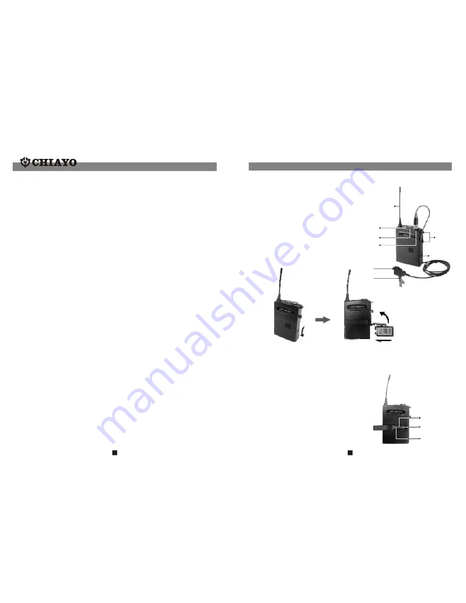
MT
Channel
GT
Selector
Beltpack Transmitter
SM-916(UHF)
/
SM-316(VHF)
Battery installation
SM-916/SM-316 use a 9V battery. To
insert the battery, first open the battery
compartment cover by pressing the
cover downward till the door flips open
by itself (see below picture). When
installing the battery, please beware of
correct polarity. To put back the cover of
the battery compartment, one has to
press the cover in upward direction until
it is locked.
Battery status
Indic ator
Power swit ch
Audio in put
Connector
Battery
Compartment
Cable
restrain t
Mik e clip
Capsuale
Antenna(SM-916)
Channel selection and gain adjust
Channel selector and gain adjust are hidden in the designated cover of the front as
illustrated. To make channel selection and gain adjust, please press the designated
cover and flip it open as illustrated.
Channel selection can be made by
rotating the selector with a small
screw driver.
Gain adjust for Lavalier and Headset
microphones can be done by adjusting
the MT switch, whereas GT switch is
for the gain adjust of electric Guitar
and other high- impedance line level
inputs.
Fig.1


