


WIRING DIAGRAMS 11
WIRING DIAGRAMS 12
With the low current and voltage levels found in some
circuits, it is important that the best possible bond at all
wire splices be made by soldering the splices.
Use care when probing the connections or replacing
terminals in them, it is possible to short between opposite
terminals. If this happens to the wrong terminal part, it is
p o s s i b l e that d a m a g e may be d o n e to c e r t a i n
c o m p o n e n t s . Always use j u m p e r wires between
connectors for circuit checking. Never probe through the
Weather-Pack seals.
When diagnosing for possible open circuits, it is often
difficult to locate them by sight because oxidation or
terminal misalignment are hidden by the connectors.
Merely wiggling a connector on a sensor or in the wiring
harness may correct the open circuit condition. This
should always be considered when an open circuit is
indicated while troubleshooting. Intermittent problems
may also be caused by oxidized or loose connections.
METRl-PACK CONNECTORS
The Metri-Pack connectors use a pull-to-seat type
terminal, as shown in figure 19. The special tool required
to remove the terminal is J-35689-A terminal remover. If
removal is attempted with an ordinary pick, there is a
good chance that the terminal will be bent or deformed.
Refer to figure 19.
[<>] Remove or Disconnect (Figure 19)
Tool Required:
J-28742 Terminal Remover
1. Primary lock (121) by lifting.
2. Connector sections.
3. Secondary lock (125) by spreading the sides of the
hasp, thus clearing the staples and rotating the
hasp (127).
4. Terminal (131) by using J-28742 (128).
* Snip off the old terminal assembly.
5. 5 mm of the wire insulation (130).
[^]
Clean
Terminal barrel (124).
[><] Install or Connect (Figure 19)
1. Terminal insulator (134) on the wire. Slide the
insulator back on the wire about 8 cm (3 inches).
2. Terminal (131) on the wire.
* Roll crimp (132) and solder the terminal
3. Terminal insulator (134) and the roll crimp (133).
4. Terminal into the connector.
5. Secondary lock (125).
6. Connector sections until the primary lock (121)
engages.
METRI-PACK CONNECTOR REPLACEMENT
[<>] R e m o v e or Disconnect (Figure 19)
Tool Required
J-35689-A Terminal Remover
1. Primary lock (121) by lifting.
2. Connector Body (1ST).
3. Connector seat (120) by pulling the seal back onto
the wires away from the connector body (137).
Figure 18—Twin Lock Connector Terminal
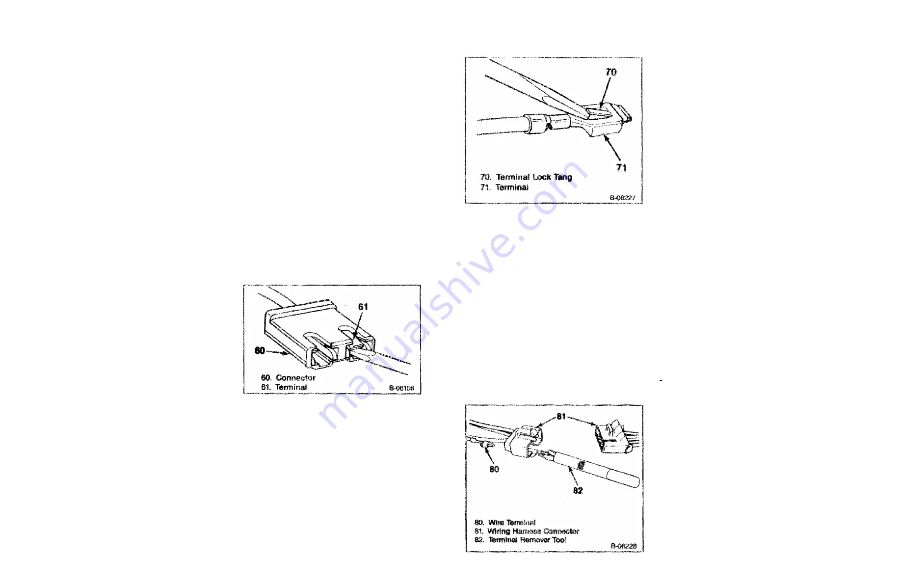
Figure 17—Resetting the Lock Tang
WEATHER-PACK CONNECTORS
Special connectors known as Weather-Pack connectors
(figure 19) require a special tool J-28742 for servicing.
This special tool is required to remove the pin and sleeve
terminals. If removal is attempted with an ordinary pick,
there is a good chance that the terminal will be bent or
deformed. Unlike standard blade-type terminals, these
terminals cannot be straightened once they are bent.
Mate sure that the connectors are property seated and
all of the sealing rings in place when connecting the
leads. The hinge-type flap provides a back-up, or
secondary locking feature for terminals. They are used to
improve the connector reliability by retaining the terminals
if the small terminal lock tangs are not positioned
properly.
Molded-on-connectors require complete replacement of
the connection. This means splicing a new connector
assembly into the harness. Environmental connections
c a n n o t b e r e p l a c e d with s t a n d a r d c o n n e c t i o n s .
Instructions are provided with the Weather-Pack
connector and terminal packages.
Figure 16—Removing the Terminals from
the Connector
WIRING CONNECTOR TERMINAL
REPLACEMENT (TWIN LOCK TYPE)
[<>] Remove or Disconnect (Figure 18)
Tool Required:
J-22727 Terminal Remover
1. Connector lock tangs.
2. Terminal lock tangs.
3. Terminal
[><] Install or Connect
1. Pry out the tangs
2. Terminal into the connector.
.
CIRCUIT MAINTENANCE
AND REPAIR
MAINTENANCE AND REPAIR
All electrical connections must be kept clean and tight.
Loose or corroded connections may cause a discharged
battery, difficult starting, dim lights, and possible damage
to the generator and regulator. Wires must bo replaced if
insulation becomes burned, cracked, or deteriorated.
To splice a wire or repair one that is frayed or broken
always use rosin flux solder to bond the splice and
insulating tape to cover all splices or bare wires.
When replacing wire, it is important that the correct size
wire be used as shown on applicable wiring diagrams or
parts book. Each harness or wire must be held securely in
place to prevent chafing or damage to the insulation due
to vibration.
Never replace a wire with one of a. smaller size or
replace a fusible link with a were of a larger size.
WRING CONNECTOR TERMINAL
REPLACEMENT (BLADE TYPE)
[<>] Remove or Disconnect (Figure 10)
1. Terminal lock tang.
2. Terminal (61).
[><] Install or Connect (Figure 17)
I. Pry up on the tang (70).
2. Terminal into the connector.
ON-VEHICLE SERVICE
Wiring harnesses are joined by using a multiple plug
and receptacle connector block, or a terminal post
chassis junction block. In the instrument panel area
plastic insulated blade-type connectors and screw-type
terminals are used.
Each harness or wire must be held securely in place by
clips or other holding devices to prevent chafing of the
insulation.
WIRE SIZE
Wire size in a circuit is determined by the amount of
current, the length of the circuit and the voltage drop
allowed. Wire size is specified using the metric gage. The
metric gage describes the wire size directly in cross
section area measured in square millimeters.
WIRE SIZE
CONVERSION TABLE
METRIC AWG
SIZE SIZE
(mm)
2
0.22 24
0.35 22
0.5 20
0.8 18
1.0 16
2.0 14
3.0 12
5.0 10
8.0 8
13.0 6
19.0 4
32.0 2
40.0
1
50.0
0
62.0
00
Summary of Contents for P 1989
Page 10: ......
Page 11: ......
Page 12: ......
Page 13: ......
Page 14: ......
Page 15: ......
Page 16: ......
Page 19: ......
Page 20: ......
Page 21: ......
Page 23: ......
Page 26: ...2 2 0 RED THERMO HW FUSIBLE LINK 2 8 BLK RED 30 2 O m I C H m 3 2 m 3 0 z 1...
Page 28: ......
Page 29: ...15 8 BLK TO A C COMP l P CLUSTER CONN FUSE BLOCK IGNITION L 2 5 V 6 SECTION A PAGE 21...
Page 32: ...l P CLUSTER CONN TO GENERATOR IGNITION L05 L19 V 8 SECTION A PAGE 24 FUSE BLOCK REAR...
Page 34: ...HOT FUEL HANDLING HOT FUEL HANDLING L05 L1 9 V8 SECTION A PAGE 26...
Page 35: ......
Page 36: ......
Page 37: ......
Page 38: ......
Page 39: ......
Page 41: ......
Page 42: ......
Page 49: ...TO ECM ELECTRONIC CONTROL MODULE OUTPUTS L05 L19 V8 SECTION A PAGE 41...
Page 52: ......
Page 53: ......
Page 54: ......
Page 71: ......
Page 72: ...TO ROOF MARKER LPS RPO 401 9 8 BRN 9 8 BRN RADIO EQUIPMENT RPO UM6 UP8 SECTION A PAGE 64...
Page 74: ......
Page 77: ...150 1 0 BLK C0 m g o z im o o 30 m 3D O m n O G C D m 30 30 O o o C O...
Page 86: ......
Page 93: ......
Page 97: ...START IGNITION LT9 V8 BODY S TY LE 42 SECTION B PAGE 4 FRONT REAR...
Page 99: ...POWER DISTRIBUTION L25 BODY STYLE 4 2 SECTION B PAGE 6 FRONT FUSE BLOCK REAR...
Page 100: ...FUSE BLOCK REAR POWER DISTRIBUTION LE8 V 8 BODY S TY LE 32 SECTION B PAGE 7...
Page 101: ...POWER DISTRIBUTION LT9 V 8 BODY STYLE 4 2 SECTION B PAGE 8 FUSE BLOCK REAR...
Page 102: ...32 BLK BATT CABLE FRONT FUSE BLOCK REAR POWER DISTRIBUTION L 0 5 V 8 SECTION B PAGE 9...
Page 113: ...START IGNITION L05 V8 SECTION B PAGE 20...
Page 121: ...CD FUEL SHUT OFF VALVE 12020274 GLOW PLUGS LL4 DIESEL SECTION B PAGE 28...
Page 126: ...TO ECM 439 8 PNK BLK ELECTRONIC CONTROL MODULE L05 V8 SECTION B PAGE 33...
Page 137: ...X...
Page 138: ...r...
Page 139: ...s...
Page 140: ...s...
Page 141: ......
Page 142: ...i a...
Page 143: ......


