background image

Cross Slide and Compound Rest 

 
The graduations on the handwheel is in millimetres.  The dovetails have been fitted with gibs 
to allow for adjustments to be made.  Make sure that the dovetails are clean and are greased 
thoroughly before any adjustments. 
To adjust the gib strips, first loosen the rear set screw and then turn the front screw until the 
slide moves smoothly without backlash, before tightening the rear set screw.  Provision has 
been made for the elimination of the backlash in the cross-slide nut.  Remove the dust plate 
mounting on the rear face of the carriage groove.  Turn the cross slide handwheel to move 
the  cross-feed  nut  until  it  reached  the  end  edge  of  the  feed  leadscrew  and  then  turn  the 
socket  screw  clockwise  as  required.    A  45

  turn  of  the  socket  screw  eliminates  approx. 

0.125mm of backlash.  Keep checking the cross slide until the backlash moves smoothly. 
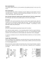
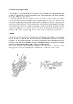
 

Tailstock 

 
The tailstock can be moved freely on the bed and clamped at any position by using the locking 
lever A, the tailstock quill can also be moved forwards and backwards and locked in position 
using lever B.  For precise adjustment, the tailstock can be adjusted in the cross direction by 
turning the socket screw clockwise or counter clockwise as required.  Release the clamping 
lever A and adjust the setscrews on either side of the tailstock body. 
Place a steel bar that is approx. 300mm in length between the centres and measure with a 
dial gauge mounted on the saddle to see if the distances on both ends are the same. 


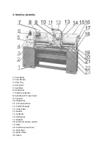
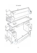
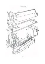
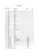
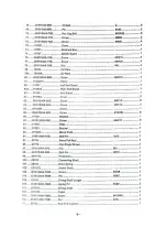
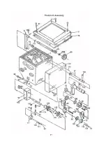
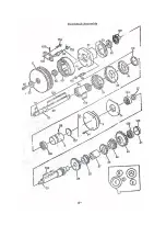
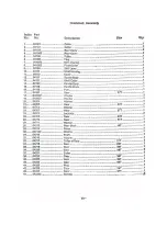
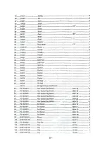
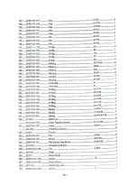
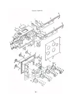
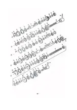
Summary of Contents for Coventry Pro

Page 1: ...Coventry Pro Lathe Operation Manual Chester UK Ltd Clwyd Close Hawarden Industrial Park Hawarden Chester CH5 3PZ Tel 01244 531631 sales chestermachinetools com www chestermachinetools com...

Page 2: ...al Safety Rules 2 Safety Rules for Lathes 3 Specification 4 Machine Breakdown 5 Unpacking 6 Lubrication 7 Spindle Speed Control 8 Operation 9 Thread and Feed Selection 10 Electrical System 11 Parts Li...

Page 3: ...se 9 Do not force a tool to complete a job it was not designed to do 10 Wear the correct clothing and safety items do not wear loose clothing gloves ties or jewellery that could be caught in the movin...

Page 4: ...p fingers away from any rotating parts and cutting tools while in operation 4 Never force a cutting action 5 Never perform an abnormal or little used operation without study and the use of adequate bl...

Page 5: ...224mm Swing over the Gap 500mm 500mm Centre Height 178mm 178mm Distance between Centres 500mm 750mm Bed Width 186mm 186mm Bed Height 294mm 294mm Motor Output 1 5kW 2 hp 1 5kW 2 hp Spindle Bore 38mm 38...

Page 6: ...Box 6 Headstock 7 Electrical Cabinet 8 Spindle with 3 Jaw Chuck 9 Toolpost 10 Worklamp 11 Compound Rest 12 Coolant Supply 13 Cross Slide 14 Saddle 15 Tailstock 16 Guideway 17 Bracket 18 Forward rever...

Page 7: ...ite spirit or kerosene to clean all of the bright metal surfaces do not use lacquer thinner or any other caustic solvents which could damage the paint work Once the machine is clean apply a thin layer...

Page 8: ...Check the oil level frequently and top the oil level up if needed The first oil change should be made after 3 months and then annually Apron The oil bath is filled with ISO32 oil through the filling...

Page 9: ...perial Thread Right hand thread and Longitudinal feed toward the headstock side Left Figure Left hand thread and longitudinal feed toward the tailstock side Right figure Feed Left Figure Thread Right...

Page 10: ...eed selector 2 pieces 18 Thread cutting engagement lever 9 Compound rest lock 19 Feed axis selector 10 Tool post clamping lever 10 Spindle Speed Control Ensure that the lubrication has been carried ou...

Page 11: ...stop the machine and investigate If everything is normal gradually increase the spindle speed Operation Only ever use high peripheral speed rated chucks with this machine The maximum spindle speed for...

Page 12: ...eed selector levers to engage the feed speeds to start the feed rod If the feed lever on the apron is then used pushing the lever upwards will engage the cross feed downwards engages the longitudinal...

Page 13: ...ched the end edge of the feed leadscrew and then turn the socket screw clockwise as required A 45 turn of the socket screw eliminates approx 0 125mm of backlash Keep checking the cross slide until the...

Page 14: ...main power switch and make sure that the machine is correctly grounded When viewed from the pulley side the main motor must run in a clockwise direction the spindle must run in a counter clockwise dir...

Page 15: ...mp JC11 1 SB1 Button LA38 20913 SB2 Button LA38 11 209 SA1 Button LAY3 11X 2 HL Indicator Light AD11 21 8GZ SQ1 Limit Switch LXW5 11G2 L SQ2 Limit Switch LXW5 11G2 L SQ3 Limit Switch LXW5 11G2 L SQ4 L...

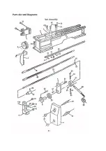
Page 16: ...Parts List and Diagrams...

Page 17: ......

Page 18: ......

Page 19: ......

Page 20: ......

Page 21: ......

Page 22: ......

Page 23: ......

Page 24: ......

Page 25: ......

Page 26: ......

Page 27: ......

Page 28: ......

Page 29: ......

Page 30: ......

Page 31: ......

Page 32: ......

Page 33: ......

Page 34: ......

Page 35: ......

Page 36: ......

Page 37: ......

Page 38: ......

Page 39: ......

Page 40: ......

Page 41: ......

Page 42: ......

Page 43: ......

Page 44: ......

Page 45: ......

Page 46: ......

Page 47: ......

Page 48: ......

Page 49: ......

Reviews: