Chery Tiggo 2009 Service Manual Download Page 1157

Turn ignition switch on, with the scan tool, view and erase stored DTCs in the TCM.

Start engine and warm it to normal operating temperature, then select

D

position.

Drive the vehicle in 1st, 2nd, 3rd and 4th gears.

With the scan tool, select view DTC and data stream.

If the DTC is detected, the DTC condition is current. Go to Diagnostic Procedure - Step 1.

If the DTC is not detected, the DTC condition is intermittent (See Diagnostic Help and Intermittent DTC Trou-
bleshooting in Section 08 Transaxle & Transfer Case for more information).

NOTE :

Checking the automatic transaxle fluid quality and fluid level is the most basic check of the automatic transaxle. The
fluid check is also an important inspection to determine if the transaxle will need to be disassembled.

CAUTION:
The burnt scent of ATF fluid indicates that the transaxle fluid is contaminated. The tiny particles in
the fluid pan indicate that the transaxle is worn out and it will be necessary to overhaul the trans-
axle.

NOTE :
While performing electrical diagnosis & testing, always refer to the electrical schematics for specific circuit
and component information.

Diagnostic Procedure

1.

CHECK FLUID QUALITY AND FLUID LEVEL AND DTC

Drive the vehicle, until the ATF reaches operating temperature (70° - 80°C).

Park the vehicle on level ground.

Shift the gear selector lever to all gear positions once, then shift to gear “N”.

Clean and check the outside of the dipstick and remove the dipstick to check the fluid level.

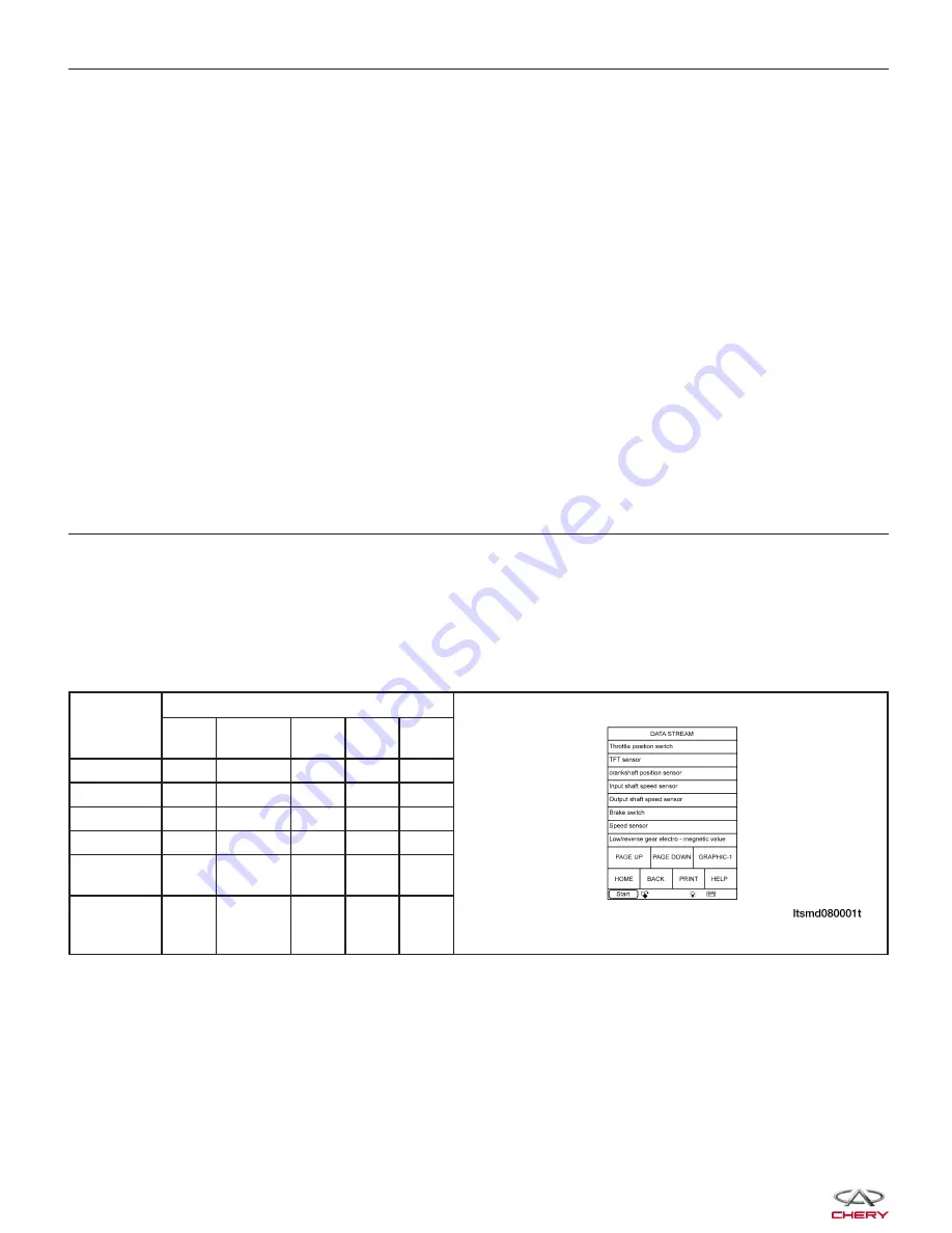
With the scan tool, select view DTC and data stream for A/T.

Start the engine.

Monitor the value of the gear position as indicated in the following table while driving:

GEAR

POSITION

ELECTRO-MAGNETIC VALVE

L/R

GEAR

2

UD

OD

DCC

(REF)

Gear 1

Off

On

Off

On

Off

Gear 2

On

Off

Off

On

On

Gear 3

On

Off

Off

Off

On

Gear 4

On

Off

On

Off

On

Reverse

gear

Off

On

On

On

Off

Neutral

gear/

Parking

Off

On

On

On

Off

Is DTC 22 or 23 present?

Yes

>>

If DTC 22 present, see diagnostic procedure for DTC 22 in 08 - Transaxle & Transfer Case
If DTC 23 present, see diagnostic procedure for DTC 23 in 08 - Transaxle & Transfer Case.

No

>>

Go to the next step.

DIAGNOSIS & TESTING

08–

214

Chery Automobile Co., Ltd.

Summary of Contents for Tiggo 2009

Page 1: ...of this manual without obligation or advance notice All rights reserved No part of this book may be reproduced or used in any form or by any means electronic or mechanical including photocopying and r...

Page 2: ...ns 01 2 VEHICLE SERVICE PREPARATION 01 3 Preparation For Vehicle Service 01 3 Tools and Testing Equipment 01 3 Special Tools 01 3 Disconnection of the Negative Battery Cable 01 4 PROPER SERVICE PRACTI...

Page 3: ...stallation instructions Integrated torque specifications Integrated illustrations Component specifications Diagnostic Procedures The diagnostic procedures are grouped into the following Diagnostic Tro...

Page 4: ...Tools and Testing Equipment Be sure that all necessary tools and measuring equipment are available before starting any work Inspect the vehicle and reference any needed ser vice information before sta...

Page 5: ...nd then wait two minutes to allow the backup supply of the air bag diagnostic monitor unit to deplete its stored power Disconnecting the battery cable deletes the memo ries of the clock audio and DTCs...

Page 6: ...eign material from entering Component Disassembly If the disassembly procedure is complex requiring many parts to be disassembled make sure that all parts are disassembled in a way that will not affec...

Page 7: ...ressed air can cause dirt and other particles to fly out causing injury to the eyes Wear protective eyewear whenever using compressed air Component Reassembly Standard values such as torques and certa...

Page 8: ...ng components of parts Apply specified oil or grease at the prescribed locations such as oil seals before reassembly reassembly Adjustments Use suitable gauges and testers when making adjustments Rubb...

Page 9: ...namometer Place a fan preferably a vehicle speed proportional type in front of the vehicle Connect an exhaust gas ventilation unit WARNING Exhaust gases can injure or kill They contain carbon monoxide...

Page 10: ...VEHICLE IDENTIFICATION NUMBER VIN 01 10 VIN Location 01 10 VIN Identification Codes 01 11 INTERNATIONAL SYMBOLS 01 13 International Symbols 01 13 FASTENER USAGE 01 14 Fastener Usage 01 14 01 01 9 Cher...

Page 11: ...The VIN is printed on a plastic tag attached to the top right corner of the upper instrument panel The VIN is also found on the vehicle certification VC label Vehicle Identification Number VIN Tag Loc...

Page 12: ...ented by the letter D Digit 5 The fifth digit of the VIN code represents the body configuration of the vehicle A represents three compartments five door and 4X2 B represents two compartments five door...

Page 13: ...ugh computation after confirming the other six teen digits of the VIN Digit 10 The tenth VIN position represents the model year code 5 represents the year 2005 Digit 11 The eleventh VIN position repre...

Page 14: ...bols 1 High Beam 2 Fog Lamps 3 Headlamp Parking Lamps Panel Lamps 4 Turn Signals 5 Hazard Warning 6 Front Windshield Washer 7 Front Windshield Wiper 8 Front Windshield Wiper and Washer 9 Front Windshi...

Page 15: ...onal injury or death Fasteners and torque specification references in this Service Manual are identified in metric format During any maintenance or repair procedures it is important to salvage all fas...

Page 16: ...01 16 Performing Efficient Electrical Circuit Diagnosis and Troubleshooting 01 16 Electrical Circuit Simulation Tests 01 16 Precautions For Handling Control Modules and Electrical Components 01 18 Ho...

Page 17: ...service If possible re create the conditions present at the time of the incident Doing so may help avoid a No Trouble Found Diagnosis The following illustrates tests to simulate the conditions enviro...

Page 18: ...lectrical component is heat sensitive heat the component with a heat gun or equivalent CAUTION Do not heat components above 60 C 140 F If the incident occurs while heat testing the component replace o...

Page 19: ...g components Do not apply excessive force when disconnecting a connector If a connector is installed by tightening bolts loosen mounting bolt then remove it by hand When connecting components Before i...

Page 20: ...een the wire and connec tor may result Probing From Terminal Side Female Terminal Do not insert any object into the female connector that is bigger than the male terminal Male Terminal Carefully probe...

Page 21: ...ELECTRICAL SCHEMATICS 01 21 Connector Symbols 01 21 Option Splices 01 22 Electrical Schematic Example 01 23 HOW TO LOCATE ELECTRICAL SCHEMATICS IN THE SERVICE MANUAL 01 25 Electrical Schematic Index 0...

Page 22: ...shown from the harness side are enclosed by a double line and followed by the direction mark Most of the connector symbols in the wiring dia grams are shown from the terminal side In electrical schema...

Page 23: ...Option Splices Option splices are shown with solid diamond shaped boxes with identification numbers inside HOW TO READ ELECTRICAL SCHEMATICS BESMW010002T 01 22 Chery Automobile Co Ltd...

Page 24: ...Electrical Schematic Example HOW TO READ ELECTRICAL SCHEMATICS BESMW010001T 01 01 23 Chery Automobile Co Ltd...

Page 25: ...ation This represents that the circuit is optional depending on vehicle application 12 Ground GND This represents the ground connection See Ground Distribution in Section 16 Wiring Ground connector nu...

Page 26: ...nic Engine Controls Engine Control Module ECM Engine Coolant Temperature Sensor Knock Sensor Upstream Oxygen Sensor Downstream Oxygen Sensor Crankshaft Position Sensor Camshaft Position Sensor Ignitio...

Page 27: ...line Axle None 10 Suspension None 11 Steering Power Steering Switch 12 Brakes Antilock Brake System ABS Module Wheel Speed Sensors Brake Switch Parking Brake Switch Brake Fluid Level Switch 13 Heating...

Page 28: ...reviation List TERM ABBREVIATION Antilock Brake System ABS Accelerator Sensor AES Accelerator Pedal Position Sensor APS Automatic Temperature Control ATC Automatic Transaxle Fluid ATF Body Control Mod...

Page 29: ...nput Shaft Speed Sensor ISS Sensor Knock Sensor KS Manifold Absolute Pressure MAP Mass Air Flow MAF Malfunction Indicator Lamp MIL Oil Pressure Switch OPS Output Shaft Speed Sensor OSS Sensor Positive...

Page 30: ...l Installation 02 19 Camshaft 02 20 Removal Installation 02 20 Cylinder Head 02 23 Removal Installation 02 23 Front Crankshaft Oil Seal 02 25 Removal Installation 02 25 Rear Crankshaft Oil Seal 02 27...

Page 31: ...02 60 Specifications 02 60 Disassembly 02 60 Inspection 02 61 Assembly 02 62 CYLINDER HEAD UNIT REPAIR 02 63 Cylinder Head 02 63 Specifications 02 63 Disassembly 02 63 Inspection 02 65 Assembly 02 65...

Page 32: ...a sprocket that is located on the crankshaft The piston assembly is an aluminum piston with a cast iron con necting rod The aluminum cylinder head contains dual overhead camshafts with 4 valve per cyl...

Page 33: ...learance First Ring 0 04 0 08 mm Second Ring 0 01 0 0251 mm Connecting Rod Radial Clearance 0 016 0 051 mm Connecting Rod Axial Clearance 0 002 0 013 mm Diameter Of Crankshaft Main Journals 53 981 54...

Page 34: ...ust Valve 5 96 0 008 mm Valve Guide Inner Diameter Intake Valve 5 4 0 1 mm Exhaust Valve 5 4 0 1 mm Fringe Thickness On Top Of Valve Intake Valve 0 3 0 15 mm Exhaust Valve 0 3 0 15 mm Valve Tilt Angle...

Page 35: ...ust Manifold Nuts 25 Exhaust Manifold Heat Shield Bolts 15 Exhaust Camshaft Timing Belt Pulley Bolt 120 Flywheel Bolts manual transaxle 75 Fuel Rail Bracket Bolts 11 Idler Pulley Bolt 40 Intake Camsha...

Page 36: ...Mount Bolt Remover CH 20001 Camshaft Seal Installer CH 20002 Crankshaft Holder CH 20003 Valve Spring Compressor Adaptor CH 20004 Rear Crankshaft Oil Seal Installer CH 20005 GENERAL INFORMATION 02 02...

Page 37: ...haft Oil Seal Guide CH 20006 Front Crankshaft Seal Installer CH 20007 Front Crankshaft Seal Guide CH 20008 Camshaft Holder CH 20010 Valve Seal Installer CH 20011 GENERAL INFORMATION 02 8 Chery Automob...

Page 38: ...al Installer Guide CH 20012 Valve Seal Remover CH 20013 Valve Keeper Installer CH 20017 Valve Spring Compressor CH 20018 Crankshaft Belt Pulley Fixture CH 20019 GENERAL INFORMATION 02 02 9 Chery Autom...

Page 39: ...led passages in the crankshaft to lubricate the con necting rod bearings Controlled leakage through the crankshaft main bearings and connecting rod bearings is slung radially outward to cool and lubri...

Page 40: ...lunger 10 Flange Bolt 11 Flange Bolt 12 Oil Cooler 13 Oil Filter Connector 14 Oil Filter 15 Dowel Pin 16 Oil Pan Bolt 17 Oil Pan Bolt 18 Oil Pan Bolt 19 Oil Pan 20 O Ring 21 O Ring 22 Oil Pump Straine...

Page 41: ...et Oil Passage if equipped 6 To Cylinder Head 7 Oil Return Passage 8 To Front Bearing Cap 9 To Middle Bearing Cap 10 Oil Dipstick 11 To Crankcase 12 Crankcase Pipe 13 Oil Filter Bracket 14 Oil Pressur...

Page 42: ...kage 4 Faulty ignition coil s 1 Test minimum air flow Refer to Appropriate Diagnostic Information 2 Refer to Appropriate Diagnostic Information 3 Inspect intake manifold manifold gasket and vacuum hos...

Page 43: ...rrect viscosity 3 Change engine oil and filter 4 Check and correct engine oil level 5 Install new camshaft 6 Replace cylinder head 7 Grind valve seats and replace valves Connecting Rod Noise 1 Insuffi...

Page 44: ...ose fastener broken or porous metal part 3 Misaligned or deteriorated cup or threaded plug 1 Replace gasket 2 Tighten repair or replace the part 3 Replace if necessary Oil Consumption Or Spark Plugs F...

Page 45: ...a and not vary more than 25 percent from cylinder to cylinder If one or more cylinders have abnormally low compression pressures repeat the compression test If the same cylinder or cylinders repeat an...

Page 46: ...placing hands near the drive belt tensioner while it is being held 1 Drive Belt 2 Generator Bolt 3 Tensioner Pulley Bolt 4 Tensioner 5 Compressor 6 Generator 7 Idler Pulley 8 Generator Bracket 9 Gener...

Page 47: ...raise the air cleaner case upper 2 Remove the air cleaner element 3 Install a new air cleaner element 4 Installation is in the reverse order of removal Installation Notes If necessary clean the insid...

Page 48: ...r Head Cover Removal Installation 1 Disconnect the negative battery cable 2 Remove the engine cover 3 Use compressed air to blow dirt and debris off the cylinder head cover prior to removal 4 Disconne...

Page 49: ...required to perform the repair procedure CH 20002 Camshaft Seal Installer CH 20010 Camshaft Holder 1 Remove the accessory drive belt See Accessory Drive Belt Removal Installation in Section 02 Engine...

Page 50: ...N m NOTE Equally loosen camshaft bearing cap bolts in several steps 7 Remove the camshaft bearing caps and place them in proper order NOTE The camshaft bearing caps are marked for identification 8 Rem...

Page 51: ...t the camshafts from rotating in either direction Use special tool CH 20002 1 to install the camshaft seal Install the intake and exhaust camshaft bearing caps in the proper order Slowly tighten bolts...

Page 52: ...2 Engine 3 Remove the camshafts See Camshaft Removal Installation in Section 02 Engine 4 Remove intake manifold See Intake Manifold Removal Installation in Section 02 Engine 5 Remove exhaust manifold...

Page 53: ...re not damaged The cylinder head bolts should not be reused The new bolts should be examined before use If the bolts are stretched the bolts should be replaced Position the new cylinder head gasket on...

Page 54: ...required to perform the repair procedure CH 20007 Front Crankshaft Seal Installer CH 20008 Front Crankshaft Seal Guide CH 20019 Crankshaft Belt Pulley Fixture 1 Remove the accessory drive belt See Acc...

Page 55: ...ol and remove the front crankshaft oil seal 1 CAUTION Be careful not to damage the front cover seal surface while removing the seal 7 Installation is in the reverse order of removal Installation Notes...

Page 56: ...ssembly See Transaxle Assembly Removal Installation in Section 08 Transaxle Transfer Case 2 Using special tool CH 20043 1 hold the flywheel 3 Remove the clutch pressure plate retaining bolts 1 and the...

Page 57: ...ling seal lubricate seal guide with clean engine oil Position the seal over the rear crankshaft seal guide Use special tool CH 20005 2 CH 20006 1 to install the rear crankshaft oil seal Ensure that th...

Page 58: ...engine hoist 3 Remove the air cleaner housing See Air Cleaner Housing Removal Installation in Section 02 Engine 4 Remove the air cleaner housing base tray 5 Remove the engine left mount retaining bolt...

Page 59: ...en Engine right mount bolts to 70 N m 4 Installation is in the reverse order of removal Removal Installation Front Mount NOTE The following special tools are required to perform the repair procedure E...

Page 60: ...le hood 2 Remove the negative battery cable from the engine 3 Remove the engine cover 4 Remove the battery battery hold downs and battery tray See Battery Removal Installation in Section 05 Starting C...

Page 61: ...e fuel pressure See Fuel Pressure Relief Procedure in Section 04 Fuel Delivery 11 Disconnect and remove the fuel line at the fuel rail 12 Remove the air inlet hose and the air cleaner case assembly NO...

Page 62: ...e Throttle body control A C compressor Oil pressure sensor Power steering pump pressure switch Generator 15 Remove the pipe from the canister control valve 1 16 Disconnect the heater hoses 1 on the ve...

Page 63: ...bris from entering the A C system 23 Remove the high pressure line 1 and low pres sure line 2 from the power steering pump drain fluid from lines Tighten High pressure line to power steering pump 40 5...

Page 64: ...n 09 Driveline Axle 29 Drain the engine oil 30 Lower the vehicle and install engine lift chain hangers 31 Remove the bolts 1 securing the front engine mount Tighten Engine front mount bolt to 60 N m 3...

Page 65: ...Engine right mount bolt to 70 N m 35 Verify all components between the engine and vehicle are disconnected 36 Remove the front sub frame See Front Sub Frame Removal Installation in Section 10 Suspensi...

Page 66: ...g Charging 41 Remove the A C compressor pipe 42 Remove the A C compressor 2 See A C Com pressor Removal Installation in Section 13 Heat ing Air Conditioning 43 Remove the power steering pump 1 with th...

Page 67: ...oling system is hot The cooling system is under pressure steam and hot liquid can come out forcefully when the cap is loosened slightly Failure to follow these instructions may result in serious perso...

Page 68: ...ne right mount bolts 1 and bracket Tighten Engine right mount bolts to 70 N m 5 Remove the accessory drive belt See Accessory Drive Belt Removal Installation in Section 02 Engine 6 Remove the cranksha...

Page 69: ...rankshaft until the crankshaft tool completely holds the crankshaft in place Tighten Crankshaft holder to 28 N m NOTE The crankshaft holder will prevent the crankshaft from rotating in either directio...

Page 70: ...tension to the belt and align the finger pointer of the ten sioner to the middle of the U slot opening Tighten the tensioner pulley bolt 1 to 30 N m then tighten the intake and exhaust camshaft pulle...

Page 71: ...ect the catalytic converter assembly from the manifold 6 Remove the exhaust manifold nuts 1 Tighten Exhaust manifold nuts to 25 N m 7 Remove and discard manifold gasket 1 8 Installation is in the reve...

Page 72: ...ing system is under pressure steam and hot liquid can come out forcefully when the cap is loosened slightly Failure to follow these instructions may result in serious personal injury 4 Remove the cool...

Page 73: ...ressure sensor electrical con nector 1 1 6L engine 9 Remove MAP sensor 2 from intake manifold 10 Loosen the clamp between the air intake hose and the air cleaner 11 Loosen the clamp between the air in...

Page 74: ...e switch connect 4 20 Remove the nuts 1 securing the intake manifold to cylinder head Tighten Intake manifold nuts to 11 N m 21 Installation is in the reverse order of removal Installation Notes Clean...

Page 75: ...kin wash it off immediately with water In addition used engine oil contains potentially harmful contaminants which may cause skin cancer Always use adequate skin protection when performing vehicle ser...

Page 76: ...ighten Oil pan bolts to 18 N m 5 Using a putty knife loosen seal around oil pan 6 Remove the oil pan 7 Installation is in the reverse order of removal Installation Notes Oil pan sealing surfaces must...

Page 77: ...Tighten Crankshaft timing belt pulley bolt to 130 N m and an additional 65 5 Remove the key way from the crankshaft 6 Using an appropriate tool remove the front crank shaft oil seal 1 7 Remove the fo...

Page 78: ...on in Section 02 Engine 3 Remove the oil strainer retaining bolts 1 Tighten Oil strainer bolts to 18 N m 4 Carefully remove the oil strainer 5 Installation is in the reverse order of removal Installat...

Page 79: ...r Block Bolts 23 Clearance Specifications DESCRIPTION SPECIFICATION mm Surface Distortion Limit 0 15 Inner Diameter Standard 81 Out Of Round 0 008 Taper 0 01 Disassembly 1 Remove the oil pan and then...

Page 80: ...bly 1 out through the top of the cylinder block 7 Remove the connecting rod bearings See Con necting Rod Removal Installation in Section 02 Engine CAUTION When removing the connecting rod side bearing...

Page 81: ...be replaced and new pistons and rings fitted Measure the cylinder bore at three levels in directions X and Y Top measurement should be 10 mm down and bottom measurement should be 10 mm up from bottom...

Page 82: ...on Ring Groove DESCRIPTION SPECIFICATION mm First Ring 0 04 0 08 Second Ring 0 01 0 0251 Clearance Specifications Piston Ring End Gap DESCRIPTION SPECIFICATION LIMIT First Ring End Gap 0 2 0 4 mm 0 8...

Page 83: ...om piston Clean ring grooves of any carbon deposits CAUTION Before removing the piston rings 1 check the piston ring side clearance Be careful to mark the location of the piston rings if they are to b...

Page 84: ...table tool Connecting Rod Piston Disassembly Remove the piston from the connecting rod Inspection Check the piston diameter PISTON DIAMETER All Pistons 80 946 80 964 mm ENGINE UNIT REPAIR BESM020049 B...

Page 85: ...G GROOVE CLEARANCE First Ring 0 04 0 08 mm Second Ring 0 01 0 0251 mm Wipe the cylinder bore clean Insert ring and push down with piston to ensure it is square in the bore The ring gap measurement mus...

Page 86: ...ll end PISTON PIN CLEARANCE Piston and Piston Pin 0 002 0 013 mm Assembly 1 Install the piston to the connecting rod Assemble the components in their original positions 2 Using a piston ring expander...

Page 87: ...learance 0 016 0 051 Connecting Rod Axial Clearance 0 002 0 013 Disassembly 1 Remove the connecting rod cap bolts 2 Remove the connecting rod bearing cap 3 Using a hammer handle or similar tool push t...

Page 88: ...alling the NEW rod bolts the threads and under the bolt head should be oiled with clean engine oil 2 Install each bolt finger tight then alternately tighten each bolt to assemble the cap properly 3 Ti...

Page 89: ...ssembly 1 Remove the front crankshaft oil seal See Front Crankshaft Oil Seal Removal Installation in Section 02 Engine 2 Remove the rear crankshaft oil seal See Rear Crankshaft Oil Seal Removal Instal...

Page 90: ...and bearing Install the crankshaft Cut the plastic gauge to the same width as the bearing and then put it onto the crankshaft journal to make it parallel with the central line of the crank shaft Insta...

Page 91: ...r block and lower cylinder block NOTE Identify and number the bearings if reusing them so that they are assembled in the same position and direction 2 Assemble the crankshaft and main bearings in the...

Page 92: ...0 04 Intake Valve Deflection 0 02 Exhaust Valve Deflection 0 04 Spring Height 47 7 Disassembly NOTE The following special tools are required to perform the repair procedure CH 20011 Valve Seal Instal...

Page 93: ...ing retainer 2 and valve spring 3 5 Push the valve stem from the cylinder head and remove the valve 4 6 Using special tool CH 20013 1 remove the valve oil seal 7 Remove the valve guide 8 Remove the sp...

Page 94: ...that they have been rotating Check the valve guide height Assembly 1 Install new valve guide if necessary 2 Install new valve seat if necessary 3 Using special tool CH 20011 1 and CH 20012 2 install...

Page 95: ...amshaft Specifications Camshaft Specifications DESCRIPTION SPECIFICATION mm Intake Cam Lobe Height 37 15 Exhaust Cam Lobe Height 37 05 Journal 1 Outer Diameter 31 934 31 95 Journal 2 3 4 5 Outer Diame...

Page 96: ...TE The camshaft bearing caps are marked for identification 3 Remove the camshafts and then remove the camshaft seals Inspection Measure the camshaft cam lobe height If wear is beyond the limit replace...

Page 97: ...R DIAMETER OF CAMSHAFT BEARING Cam Bearing 1 Inner Diameter 32 32 025 mm Cam Bearing 2 3 4 5 Inner Diameter 24 24 021 mm Calculation of camshaft journal clearance Journal clearance inner diameter of c...

Page 98: ...fts in place NOTE The camshaft holder will prevent the camshafts from rotating in either direction 2 Installation is in the reverse order of removal Installation Notes Install the intake and exhaust c...

Page 99: ...uide Clearance 0 032 0 063 Disassembly NOTE The following special tools are required to perform the repair procedure CH 20011 Valve Seal Installer CH 20012 Valve Stem Seal Installer Guide CH 20013 Val...

Page 100: ...ct the valves for the following Clean all valves thoroughly and discard burned warped and cracked valves Check valve seats and valve faces for damage When reconditioning valves follow the specificatio...

Page 101: ...ECTION LIMIT DIAL GAUGE READING Intake 0 02 mm Exhaust 0 04 mm If it exceeds the limit check valve to valve guide clearance Measure valve stem diameter and valve guide inner diameter Check that cleara...

Page 102: ...TION mm Spring Free Length 47 7 Spring Height At 620 Newtons Of Pressure 32 0 Disassembly NOTE The following special tools are required to perform the repair procedure CH 20011 Valve Seal Installer CH...

Page 103: ...gs should be tested for correct load Discard the springs that do not meet specifications The following specifications apply to both intake and exhaust valve springs VALVE SPRING LENGTH HEIGHT Spring F...

Page 104: ...rs 3 Using valve spring compressor CH 20018 1 com press the valve springs 4 Install the valve keepers 5 Strike the valve stem lightly with a plastic hammer after installation to verify proper assembly...

Page 105: ...2 112 Removal Installation 02 112 Exhaust Manifold 02 115 Removal Installation 02 115 Intake Manifold 02 117 Removal Installation 02 117 Idler Pulley 02 119 Removal Installation 02 119 Oil Filter 02 1...

Page 106: ...nnecting rod The aluminum cylinder head contains dual overhead camshafts with 4 valve per cylinder construction The valves are arranged in two in line banks The cylinder head incorporates powdered met...

Page 107: ...Clearance Of Crankshaft 0 0035 0 034 mm Coaxality Crankshaft Main Journal 0 005 mm Thrust Washer Thickness 2 4 2 405 mm Oil Clearance Of Crankshaft Rod and Main Journals 0 022 mm 0 058 mm Cylinder Hea...

Page 108: ...ccessory Drive Belt Tensioner Pulley Bolt 35 Camshaft Bearing Cap Bolts 11 Clutch Pressure Plate Bolts 25 Connecting Rod Cap Bolts 1st Step Tighten the bolt to 25 N m 2nd Step Tighten the bolt an addi...

Page 109: ...10 Intake Manifold Nuts 11 Intake Manifold Bracket Bolts 25 Lower Idler Pulley Bolt 45 Lower Cylinder Block Bolts 23 Oil Filter 25 Oil Pan Bolts 18 Oil Drain Plug 40 Oil Strainer Bolts 18 Oil Pump Bo...

Page 110: ...Mount Bolt Remover CH 20001 Camshaft Seal Installer CH 20002 Crankshaft Holder CH 20003 Valve Spring Compressor Adaptor CH 20004 Rear Crankshaft Oil Seal Installer CH 20005 GENERAL INFORMATION 02 02...

Page 111: ...haft Oil Seal Guide CH 20006 Front Crankshaft Seal Installer CH 20007 Front Crankshaft Seal Guide CH 20008 Camshaft Holder CH 20010 Valve Seal Installer CH 20011 GENERAL INFORMATION 02 82 Chery Automo...

Page 112: ...al Installer Guide CH 20012 Valve Seal Remover CH 20013 Valve Keeper Installer CH 20017 Valve Spring Compressor CH 20018 Crankshaft Belt Pulley Fixture CH 20019 GENERAL INFORMATION 02 02 83 Chery Auto...

Page 113: ...led passages in the crankshaft to lubricate the con necting rod bearings Controlled leakage through the crankshaft main bearings and connecting rod bearings is slung radially outward to cool and lubri...

Page 114: ...lunger 10 Flange Bolt 11 Flange Bolt 12 Oil Cooler 13 Oil Filter Connector 14 Oil Filter 15 Dowel Pin 16 Oil Pan Bolt 17 Oil Pan Bolt 18 Oil Pan Bolt 19 Oil Pan 20 O Ring 21 O Ring 22 Oil Pump Straine...

Page 115: ...et Oil Passage if equipped 6 To Cylinder Head 7 Oil Return Passage 8 To Front Bearing Cap 9 To Middle Bearing Cap 10 Oil Dipstick 11 To Crankcase 12 Crankcase Pipe 13 Oil Filter Bracket 14 Oil Pressur...

Page 116: ...kage 4 Faulty ignition coil s 1 Test minimum air flow Refer to Appropriate Diagnostic Information 2 Refer to Appropriate Diagnostic Information 3 Inspect intake manifold manifold gasket and vacuum hos...

Page 117: ...rrect viscosity 3 Change engine oil and filter 4 Check and correct engine oil level 5 Install new camshaft 6 Replace cylinder head 7 Grind valve seats and replace valves Connecting Rod Noise 1 Insuffi...

Page 118: ...ose fastener broken or porous metal part 3 Misaligned or deteriorated cup or threaded plug 1 Replace gasket 2 Tighten repair or replace the part 3 Replace if necessary Oil Consumption Or Spark Plugs F...

Page 119: ...a and not vary more than 25 percent from cylinder to cylinder If one or more cylinders have abnormally low compression pressures repeat the compression test If the same cylinder or cylinders repeat an...

Page 120: ...placing hands near the drive belt tensioner while it is being held 1 Drive Belt 2 Generator Bolt 3 Tensioner Pulley Bolt 4 Tensioner 5 Compressor 6 Generator 7 Idler Pulley 8 Generator Bracket 9 Gene...

Page 121: ...al Air Cleaner Element Removal Installation 1 Unhook the air cleaner case side clips 1 and raise the air cleaner case upper 2 Remove the air cleaner element 3 Install a new air cleaner element 4 Insta...

Page 122: ...s base 5 Remove the air cleaner housing 6 Remove the air cleaner base 7 Installation is in the reverse order of removal Cylinder Head Cover Removal Installation 1 Disconnect the negative battery cable...

Page 123: ...Removal Installation NOTE The following special tools are required to perform the repair procedure CH 20002 Camshaft Seal Installer 1 Remove the accessory drive belt See Accessory Drive Belt Removal...

Page 124: ...N m NOTE Equally loosen camshaft bearing cap bolts in several steps 7 Remove the camshaft bearing caps and place them in proper order NOTE The camshaft bearing caps are marked for identification 8 Rem...

Page 125: ...t the camshafts from rotating in either direction Use special tool CH 20002 1 to install the camshaft seal Install the intake and exhaust camshaft bearing caps in the proper order Slowly tighten bolts...

Page 126: ...2 Engine 3 Remove the camshafts See Camshaft Removal Installation in Section 02 Engine 4 Remove intake manifold See Intake Manifold Removal Installation in Section 02 Engine 5 Remove exhaust manifold...

Page 127: ...re not damaged The cylinder head bolts should not be reused The new bolts should be examined before use If the bolts are stretched the bolts should be replaced Position the new cylinder head gasket on...

Page 128: ...e required to perform the repair procedure CH 20007 Front Crankshaft Seal Installer CH 20008 Front Crankshaft Seal Guide CH 20019 Crankshaft Belt Pulley Fixture 1 Remove the accessory drive belt See A...

Page 129: ...e the new front seal with engine oil prior to assembly Use the front crankshaft seal installer CH 20007 1 to install the new seal Rear Crankshaft Oil Seal Removal Installation NOTE The following speci...

Page 130: ...the fly wheel bolts 1 and then remove the flywheel Tighten Flywheel bolts to 75 N m 5 If equipped with automatic transaxle remove the drive plate retaining bolts 1 and then remove drive plate Tighten...

Page 131: ...Position the seal over the rear crankshaft seal guide Use special tool CH 20005 2 and CH 20006 1 to install the rear crankshaft oil seal Ensure that the lip of the seal is facing toward the crankcase...

Page 132: ...t the engine with the engine hoist 3 Remove the air cleaner housing See Air Cleaner Housing Removal Installation in Section 02 Engine 4 Remove the engine left mount retaining bolts 2 and remove the en...

Page 133: ...Engine right mount bolts to 70 N m 4 Installation is in the reverse order of removal Removal Installation Front Mount NOTE The following special tools are required to perform the repair procedure Eng...

Page 134: ...moval Installation NOTE The following special tools are required to perform the repair procedure CH 20001 Right Engine Mount Bolt Remover Engine Hoist NOTE The engine is removed with the transaxle as...

Page 135: ...uctions may result in serious personal injury 7 Remove the coolant fan radiator assembly See Coolant Fan Radiator Assembly Removal Installation in Section 06 Cooling 8 Remove the starter motor wiring...

Page 136: ...ompressor Oil pressure sensor Power steering pump pressure switch Generator 14 Remove the pipe from the canister control valve 1 15 Disconnect the heater hoses 1 on the vehicle 16 Remove the vacuum li...

Page 137: ...Remove the high pressure line 1 and low pres sure line 2 from the power steering pump drain fluid from lines Tighten High pressure line to power steering pump 40 5 N m Tighten Low pressure line to po...

Page 138: ...on 09 Driveline Axle 28 Drain the engine oil 29 Lower the vehicle and install engine lift chain hangers 30 Remove the bolts 1 securing the front engine mount Tighten Engine front mount bolt to 60 N m...

Page 139: ...Engine right mount bolt to 70 N m 34 Verify all components between the engine and vehicle are disconnected 35 Remove the front sub frame See Front Sub Frame Removal Installation in Section 10 Suspensi...

Page 140: ...ction 05 Starting Charging 40 Remove the A C compressor pipe 41 Remove the A C compressor 2 See A C Com pressor Removal Installation in Section 13 Heat ing Air Conditioning 42 Remove the power steerin...

Page 141: ...ing system is hot The cooling system is under pressure steam and hot liquid can come out forcefully when the cap is loosened slightly Failure to follow these instructions may result in serious persona...

Page 142: ...ine right mount bolts 1 and bracket Tighten Engine right mount bolts to 70 N m 5 Remove the accessory drive belt See Accessory Drive Belt Removal Installation in Section 02 Engine 6 Remove the cranksh...

Page 143: ...crankshaft until the crankshaft tool completely holds the crankshaft in place Tighten Crankshaft holder to 28 N m NOTE The crankshaft holder will prevent the crankshaft from rotating in either directi...

Page 144: ...y tension to the belt and align the finger pointer of the ten sioner to the middle of the U slot opening Tighten the tensioner pulley bolt 1 to 30 N m then tighten the intake and exhaust camshaft pull...

Page 145: ...converter assembly from the manifold 6 Remove the exhaust manifold nuts 1 Tighten Exhaust manifold nuts to 25 N m 7 Remove the exhaust manifold 8 Remove and discard manifold gasket 1 9 Installation i...

Page 146: ...the engine is operating or the cooling system is hot The cooling system is under pressure steam and hot liquid can come out forcefully when the cap is loosened slightly Failure to follow these instruc...

Page 147: ...n the clamp on the PCV hose and then disconnect the PCV hose 10 Remove the fuel rail bracket bolts 1 Tighten Fuel rail bracket bolts to 11 N m 11 Remove the fuel rail with the fuel injectors and set a...

Page 148: ...belt tensioner rotate the pulley counterclockwise to loosen the drive belt WARNING Avoid placing hands near the drive belt tensioner while it is being held 2 Remove the drive belt Upper Accessory Dri...

Page 149: ...gine The oil filter gasket must be removed from the engine before installing the new oil filter 2 Installation is in the reverse order of removal Installation Notes Clean all surfaces and verify the o...

Page 150: ...02 Engine 2 Remove the crankshaft vibration damper retaining bolt 1 Tighten Crankshaft vibration damper bolts to 25 N m 3 Remove the engine timing belt See Engine Timing Belt Removal Installation in...

Page 151: ...rotate the oil pump Replace the oil pump gasket Oil Strainer Removal Installation 1 Raise and support the vehicle 2 Remove the oil pan See Oil Pan Removal Installation in Section 02 Engine 3 Remove th...

Page 152: ...r Block Bolts 23 Clearance Specifications DESCRIPTION SPECIFICATION mm Surface Distortion Limit 0 15 Inner Diameter Standard 84 Out Of Round 0 008 Taper 0 01 Disassembly 1 Remove the oil pan and then...

Page 153: ...of the cylinder block 7 Remove the connecting rod bearings See Con necting Rod Removal Installation in Section 02 Engine CAUTION When removing the connecting rod side bearings note the installation p...

Page 154: ...ns and rings fitted Measure the cylinder bore at three levels in directions X and Y Top measurement should be 10 mm down and bottom measurement should be 10 mm up from bottom of bore CYLINDER BORE All...

Page 155: ...on Ring Groove DESCRIPTION SPECIFICATION mm First Ring 0 04 0 08 Second Ring 0 01 0 0251 Clearance Specifications Piston Ring End Gap DESCRIPTION SPECIFICATION LIMIT First Ring End Gap 0 2 0 4 mm 0 8...

Page 156: ...om piston Clean ring grooves of any carbon deposits CAUTION Before removing the piston rings 1 check the piston ring side clearance Be careful to mark the location of the piston rings if they are to b...

Page 157: ...table tool Connecting Rod Piston Disassembly Remove the piston from the connecting rod Inspection Check the piston diameter PISTON DIAMETER All Pistons 83 451 83 469 mm ENGINE UNIT REPAIR BESM020049 B...

Page 158: ...G GROOVE CLEARANCE First Ring 0 04 0 08 mm Second Ring 0 01 0 0251 mm Wipe the cylinder bore clean Insert ring and push down with piston to ensure it is square in the bore The ring gap measurement mus...

Page 159: ...ll end PISTON PIN CLEARANCE Piston and Piston Pin 0 002 0 013 mm Assembly 1 Install the piston to the connecting rod Assemble the components in their original positions 2 Using a piston ring expander...

Page 160: ...learance 0 016 0 051 Connecting Rod Axial Clearance 0 002 0 013 Disassembly 1 Remove the connecting rod cap bolts 2 Remove the connecting rod bearing cap 3 Using a hammer handle or similar tool push t...

Page 161: ...lling the NEW rod bolts the threads and under the bolt head should be oiled with clean engine oil 2 Install each bolt finger tight then alternately tighten each bolt to assemble the cap properly 3 Tig...

Page 162: ...assembly 1 Remove the front crankshaft oil seal See Front Crankshaft Oil Seal Removal Installation in Section 02 Engine 2 Remove the rear crankshaft oil seal See Rear Crankshaft Oil Seal Removal Insta...

Page 163: ...l clearance should be held to 0 265 mm Oil Clearance of crankshaft main journal Clean the journal and bearing Install the crankshaft Cut the plastic gauge to the same width as the bearing and then put...

Page 164: ...block and lower cylinder block NOTE Identify and number the bearings if reusing them so that they are assembled in the same position and direction 2 Assemble the crankshaft and main bearings in the r...

Page 165: ...t Valve Deflection 0 04 Spring Height 47 7 Disassembly NOTE The following special tools are required to perform the repair procedure CH 20010 Camshaft Holder CH 20011 Valve Seal Installer CH 20012 Val...

Page 166: ...ing retainer 2 and valve spring 3 5 Push the valve stem from the cylinder head and remove the valve 4 6 Using special tool CH 20013 1 remove the valve oil seal 7 Remove the valve guide 8 Remove the sp...

Page 167: ...ely in their bores and that they have been rotating Check the valve guide height Assembly 1 Install new valve guide if necessary 2 Install new valve seat if necessary 3 Using special tool CH 20011 1 a...

Page 168: ...amshaft Specifications Camshaft Specifications DESCRIPTION SPECIFICATION mm Intake Cam Lobe Height 37 15 Exhaust Cam Lobe Height 37 05 Journal 1 Outer Diameter 31 934 31 95 Journal 2 3 4 5 Outer Diame...

Page 169: ...ing caps are marked for identification 3 Remove the camshafts and then remove the camshaft seals Inspection Inspect the camshaft for the following Measure the camshaft cam lobe height If wear is beyon...

Page 170: ...R DIAMETER OF CAMSHAFT BEARING Cam Bearing 1 Inner Diameter 32 32 025 mm Cam Bearing 2 3 4 5 Inner Diameter 24 24 021 mm Calculation of camshaft journal clearance Journal clearance inner diameter of c...

Page 171: ...ts in place NOTE The camshaft holder will prevent the camshafts from rotating in either direction 2 Installation is in the reverse order of removal Installation Notes Install the intake and exhaust ca...

Page 172: ...uide Clearance 0 032 0 063 Disassembly NOTE The following special tools are required to perform the repair procedure CH 20011 Valve Seal Installer CH 20012 Valve Stem Seal Installer Guide CH 20013 Val...

Page 173: ...ct the valves for the following Clean all valves thoroughly and discard burned warped and cracked valves Check valve seats and valve faces for damage When reconditioning valves follow the specificatio...

Page 174: ...CTION LIMIT DIAL GAUGE READING Intake 0 02 mm Exhaust 0 04 mm If it exceeds the limit check valve to valve guide clearance Measure valve stem diameter and valve guide inner diameter Check that clearan...

Page 175: ...TION mm Spring Free Length 47 7 Spring Height At 620 Newtons Of Pressure 32 0 Disassembly NOTE The following special tools are required to perform the repair procedure CH 20011 Valve Seal Installer CH...

Page 176: ...eplacement valve springs should be tested for correct load Discard the springs that do not meet specifications The following specifications apply to both intake and exhaust valve springs VALVE SPRING...

Page 177: ...s 3 Using a valve spring compressor CH 20018 1 compress the valve springs 4 Install the valve keepers 5 Strike the valve stem lightly with a plastic hammer after installation to verify proper assembly...

Page 178: ...83 Engine Assembly 02 183 Removal Installation 02 183 Engine Timing Belt 02 189 Removal Installation 02 189 Inspection 02 194 Timing Belt Automatic Tensioner 02 196 Removal Installation 02 196 Inspect...

Page 179: ...sembly 02 244 Camshaft 02 245 Hydraulic Adjusters 02 245 Rocker Arms 02 246 Valve Valve Guides 02 246 Specifications 02 246 Disassembly 02 247 Valves 02 248 Valve Guides 02 250 Valve Seats 02 251 Asse...

Page 180: ...on assembly is an aluminum piston with a cast iron connecting rod The aluminum cylinder head contains a single overhead camshaft with 4 valves per cylinder construction The valves are arranged in two...

Page 181: ...Ring 0 02 0 06 0 1 No 2 Ring 0 02 0 06 0 1 End Clearance No 1 Ring 0 25 0 35 0 8 No 2 Ring 0 40 0 55 0 8 Oil Ring 0 10 0 40 1 0 Piston Pin External Diameter 22 0 Depressing Force Kg 755 1750 Depressi...

Page 182: ...Wheel Bolt 36 Lower Balance Shaft Bolt 55 Timing Belt Cover Bolts 11 Tensioner Wheel Bolt 49 Tensioner Arm Bolt 22 Tensioner Bracket 49 Timing Belt Indicator 09 Timing Belt Rear Cover 11 Upper Balance...

Page 183: ...45 Oil Pan 18 Oil Pressure Switch 10 Oil Pressure Relief Plug 45 Oil Plug 24 Oil Strainer Screw Bolts 19 Oil Filter Adapter Bolts 19 Connecting Rod Nuts 1st Step Tighten the nuts to 20 N m 2nd Step T...

Page 184: ...ng Puller Limiter MB 991603 Cylinder Cover Bolt Spanner MB 991654 Plug Spanner MD 998162 Crankshaft Front Oil Seal Duct MD 998285 Balance Shaft Bearing Puller MD 998371 GENERAL INFORMATION 02 155 Cher...

Page 185: ...er MD 998372 Crankshaft Front Oil Seal Installer MD 998375 Hydraulic Adjuster Leak Tester MD 998440 Hydraulic Adjuster Keeper MD 998441 Hydraulic Adjuster Wiring MD 998442 GENERAL INFORMATION 02 02 15...

Page 186: ...Adjuster Keeper MD 998443 Balance Shaft Bearing Installer MD 998705 Camshaft Oil Seal Installer MD 998713 Pin For Belt Gear MD 998719 Oil Pan Remover MD 998727 GENERAL INFORMATION 02 157 Chery Automob...

Page 187: ...ssor MD 998735 Automatic Tensioner Socket MD 998767 Valve Spring Compressor MD 998772 Valve Oil Seal Installer MD 998774 Crankshaft Rear Oil Seal Installer MD 998776 GENERAL INFORMATION 02 02 158 Cher...

Page 188: ...Puller MD 998778 Piston Disassembling and Assembling Tool MD 998780 Flywheel Holder MD 998781 Plug Spanner Fixer MD 998783 Upper Balance Shaft Pulley Holder MD 998785 GENERAL INFORMATION 02 159 Chery...

Page 189: ...e cylinder head From the main journals the oil is routed through cross drilled passages in the crankshaft to lubricate the con necting rod bearings Controlled leakage through the crankshaft main beari...

Page 190: ...Pump Driven Gear 4 Oil Pump Cover 5 Oil Pan 6 Oil Strainer 7 Oil Filter 8 Oil Filter Adaptor 1 Front End Cover 2 Front End Cover Pad 3 Oil Pump Rear Cover 4 Oil Pump Driven Gear 5 Oil Pump Driving Gea...

Page 191: ...Filter and Oil Filter Adaptor 1 Oil Filter Adaptor 2 Gasket 3 Pressure Limiting Valve Plunger 4 Spring 5 Spacer 6 Plug Screw 7 Oil Filter GENERAL INFORMATION LTSM020047 02 02 162 Chery Automobile Co...

Page 192: ...kage 4 Faulty ignition coil s 1 Test minimum air flow Refer to Appropriate Diagnostic Information 2 Refer to Appropriate Diagnostic Information 3 Inspect intake manifold manifold gasket and vacuum hos...

Page 193: ...orrect viscosity 3 Change engine oil and filter 4 Check and correct engine oil level 5 Install new camshaft 6 Replace cylinder head 7 Grind valve seats and replace valves Connecting Rod Noise 1 Insuff...

Page 194: ...e battery is completely charged and the engine starter motor is in good operating condition Otherwise the indicated compression pressures may not be valid for diagnostic purposes Check engine oil leve...

Page 195: ...team white smoke emitting from exhaust Coolant foaming Engine Oil Pressure Test 1 Check the engine oil level 2 Disconnect the oil pressure switch electrical connector 3 Remove the oil pressure switch...

Page 196: ...only when the engine is stopped 1 Loosen the power steering pump adjustment bolt 1 1 Power Steering Pump 2 Crankshaft Pulley 3 Idler Pulley 4 A C Compressor 5 Coolant Pump Pulley 6 Generator Pulley 7...

Page 197: ...on is in the reverse order of removal Air Cleaner Element Removal Installation 1 Loosen the air cleaner case side clamps 1 and raise the air cleaner case upper 2 Remove the air cleaner element 3 Insta...

Page 198: ...the clamp between the air intake hose and the air cleaner 4 Remove the retaining bolt 1 securing the air cleaner housing to its base Tighten Air cleaner housing retaining bolts to 10 N m 5 Remove the...

Page 199: ...ires 3 and set them aside See Spark Plug Wire Removal Installation in Section 03 Electronic Engine Controls 6 Remove the PCV tube 5 7 Remove the cylinder head cover bolts 4 Tighten Cylinder head cover...

Page 200: ...8443 Hydraulic Post Keeper 1 Rocker Shaft Retaining Bolt 2 Intake Rocker Arm Shaft 3 Rocker Arm 4 Rocker Arm 5 Rocker Shaft Spring 6 Hydraulic Adjuster 7 Rocker Arm and Rocker Shaft 8 Exhaust Rocker A...

Page 201: ...intake and exhaust rocker shaft assembly retaining bolts 2 Tighten Rocker shaft assembly bolts to 32 N m 7 Remove the rocker arm and rocker shaft assem blies CAUTION Before disassembling the rocker a...

Page 202: ...sert the hydraulic adjusters into the rocker arms Insert special tool MD 998443 1 to prevent drop ping the hydraulic adjuster during installation Assemble the rocker shaft springs to the rocker shafts...

Page 203: ...he illustration CAUTION The oil hole in the rocker shafts should be aligned with the cylinder head to ensure cor rect installation position Using special tool MD 998713 1 install the camshaft oil seal...

Page 204: ...ts See Camshaft Removal Installation in Section 02 Engine 5 Remove the intake manifold See Intake Manifold Removal Installation in Section 02 Engine 6 Remove the exhaust manifold See Exhaust Manifold...

Page 205: ...bolts are stretched the bolts should be replaced Position the new cylinder head gasket on the engine block with the part number facing up Ensure gasket is seated over the locating dowels in the block...

Page 206: ...1 Tighten Crankshaft vibration damper bolts to 25 N m 3 Remove the engine timing belt See Engine Timing Belt Removal Installation in Section 02 Engine 4 Install special tool MD 998781 1 onto the flywh...

Page 207: ...new front seal with engine oil prior to assembly Use the front crankshaft seal installer MD 998285 1 to install the new seal Tighten the crankshaft timing belt pulley bolt in the following sequence 1s...

Page 208: ...transaxle assembly See Transaxle Assembly Removal Installation in Section 08 Transaxle Transfer Case 1 Flywheel Bolt 2 Rear Flywheel Flange 3 Flywheel 4 Front Flywheel Flange 5 Crankshaft Bushing 6 R...

Page 209: ...ive plate Tighten Drive plate bolts to 75 N m 4 Remove the crankshaft rear oil seal using a suitable tool 5 Installation is in the reverse order of removal Installation Notes When installing seal lubr...

Page 210: ...procedure Engine Hoist 1 Disconnect the negative battery cable 2 Remove the air cleaner housing See Air Cleaner Housing Removal Installation in Section 02 Engine 3 Support the engine with the engine...

Page 211: ...en Engine right mount bolts to 70 N m 4 Installation is in the reverse order of removal Removal Installation Front Mount NOTE The following special tools are required to perform the repair procedure E...

Page 212: ...downs and battery tray See Battery Removal Installation in Section 05 Starting Charging 4 Remove the hood 5 Discharge air conditioning system See A C System Evacuation and Recharge in Section 13 Heat...

Page 213: ...from the cylinder head 14 Disconnect and remove the following electrical connectors Coolant temperature sensor Crankshaft position sensor Camshaft position sensor Ignition coil Four fuel injectors Air...

Page 214: ...e the vacuum line from the brake booster 18 Remove the dipstick 19 Remove the accessory drive belt See Accessory Drive Belt Removal Installation in Section 02 Engine 20 Remove the A C compressor high...

Page 215: ...the catalytic converter to exhaust manifold bolts 1 Tighten Exhaust manifold bolt to 49 5 N m 25 Remove the front axle shaft See Front Axle Shaft Removal Installation in Section 09 Driveline Axle 26 R...

Page 216: ...rear engine mount and the bolts 1 securing the mount bracket Tighten Engine rear mount bolt to 60 N m 32 Remove the bolts 2 securing the left transaxle mount and the bolts 1 securing the mount bracket...

Page 217: ...ts between the engine and vehicle are disconnected 36 Hoist the engine from vehicle CAUTION Verify all electrical connectors are disconnected prior to engine transaxle removal 37 Separate engine and t...

Page 218: ...Engine Timing Belt Removal Installation ON VEHICLE SERVICE LTSM020048 02 02 189 Chery Automobile Co Ltd...

Page 219: ...ions may result in serious personal injury 2 Attach an engine hoist to the engine 3 Raise the engine with the engine hoist just enough to support the engine 1 Right Engine Mounting Bracket 2 Spacer 3...

Page 220: ...1 Tighten Crankshaft vibration damper bolts to 25 N m 7 Remove the timing belt upper cover Tighten Timing belt upper cover bolts to 11 N m 8 Remove the timing belt lower cover Tighten Timing belt lowe...

Page 221: ...ation Notes Rotate the camshaft pulley and align the timing marks 1 with the cylinder head cover Rotate the crankshaft pulley and align the timing marks 1 with the front cover ON VEHICLE SERVICE LTSM0...

Page 222: ...hen the timing marks are aligned If the holder could not be inserted more than 20 25 mm the lower balance shaft pulley should be rotated one revolution and the timing marks should be then be aligned K...

Page 223: ...ensioner Measure distance A between the tensioner arm and the automatic tensioner Standard distance is 3 84 mm Inspection 1 Inspect the timing belt back rubber for signs of aging and glistening ON VEH...

Page 224: ...s 2 Cracks in the grooves 3 Cracks in the side of the belt 4 3 Inspect the timing belt 1 for abnormal abrasion in the side of the belt 2 4 Inspect the timing belt for abnormal abrasion 2 or teeth miss...

Page 225: ...ighten Timing belt automatic tensioner bolts to 24 N m 3 Installation is in the reverse order of removal Installation Notes Perform the following to prepare the automatic tensioner for installation Sl...

Page 226: ...ing 98 196 N m and measure the rod displace ment If the rod displacement is 1 mm larger than the standard replace the tensioner standard mea surement is 1 mm 5 Assemble the automatic tensioner with a...

Page 227: ...on in Section 02 Engine 2 Using special tool MD 998781 1 attach the tool to the flywheel 3 Remove the crankshaft pulley bolt Tighten Crankshaft pulley bolt to 120 N m 4 Using special tool MD 998778 1...

Page 228: ...35 N m CAUTION Do not allow the belt tensioner to move while tightening the bolt if the tensioner moves it could cause the belt to be overtightened Ensure that the timing marks 1 have not moved and a...

Page 229: ...embly Tighten Exhaust manifold to catalytic converter bolts to 49 5 N m 4 Disconnect the catalytic converter assembly from the manifold 5 Remove the exhaust manifold nuts Tighten Exhaust manifold nuts...

Page 230: ...t during installation Intake Manifold Removal Installation 1 Disconnect the negative battery cable 1 Inlet Manifold Gasket 2 Knock Sensor 3 Coolant Hose 4 Coolant Hose 5 Coolant Temperature Sensor 6 C...

Page 231: ...air intake hose and the throttle body and then remove the intake pipe 7 Remove the fuel rail bracket bolts Tighten Fuel rail bracket bolts to 11 N m 8 Remove the fuel rail with the fuel injectors and...

Page 232: ...m 15 Remove the intake manifold from the cylinder head 16 Remove and discard the intake manifold gasket 17 Installation is in the reverse order of removal Installation Notes Clean all surfaces of the...

Page 233: ...r 9 Upper Balance Shaft Oil Seal 10 Crankshaft Front Oil seal 11 Oil Filter Adapter Gasket 12 Oil Filter Adapter 13 Pressure Relief Valve 14 Pressure Relief Spring 15 Pressure Relief Valve Seal 16 Oil...

Page 234: ...taining bolts Tighten Oil pan bolts to 18 N m 6 Using special tool MD 998727 1 remove the oil pan NOTE Insert the special tool between cylinder block and the oil pan Do not use a screwdriver or chisel...

Page 235: ...pulley in place 16 Remove the upper balance shaft pulley bolt Tighten Upper balance shaft pulley bolt to 45 N m 17 Using special tool MD 9988778 1 remove the upper balance shaft pulley 18 Remove the f...

Page 236: ...he front of the cylinder block when disassembling the upper bal ance shaft rear bearing 2 Using special tool MB 991603 2 and MD 998705 1 install the rear bearing 3 NOTE There is NO oil hole in the rea...

Page 237: ...r 9 Upper Balance Shaft Oil Seal 10 Crankshaft Front Oil Seal 11 Oil Filter Adapter Gasket 12 Oil Filter Adapter 13 Pressure Relief Valve 14 Pressure Relief Spring 15 Pressure Relief Valve Seal 16 Oil...

Page 238: ...taining bolts Tighten Oil pan bolts to 18 N m 6 Using special tool MD 998727 1 remove the oil pan NOTE Insert the special tool between cylinder block and the oil pan Do not use a screwdriver or chisel...

Page 239: ...pulley in place 16 Remove the upper balance shaft pulley bolt Tighten Upper balance shaft pulley bolt to 45 N m 17 Using special tool MD 9988778 1 remove the upper balance shaft pulley 18 Remove the f...

Page 240: ...block 2 Using special tool MD 998705 1 MD 991603 2 remove the lower balance shaft rear bearing from the cylinder block 3 Using special tool MD 998705 2 install the rear bearing NOTE Align the oil hol...

Page 241: ...ion used engine oil contains potentially harmful contaminants which may cause skin cancer Always use adequate skin protection when performing vehicle service CAUTION When servicing the oil filter inst...

Page 242: ...l a new drain plug gasket and then install the oil pan drain plug Tighten Oil pan drain plug to 45 N m 11 Refill the engine with the specified quantity and grade of engine oil 12 Install the oil fille...

Page 243: ...dis torted and oil leaks will occur 6 Installation is in the reverse order of removal Installation Notes Oil pan sealing surfaces must be free of grease or oil Install the four oil pan corner bolts in...

Page 244: ...ont cover 6 Remove the oil pump drive gear and the driven gear 7 Remove the oil pump rear cover 8 Installation is in the reverse order of removal Installation Notes Before installing the new oil pump...

Page 245: ...e the oil pan See Oil Pan Removal Installation in Section 02 Engine 3 Remove the oil strainer retaining bolts Tighten Oil strainer bolts to 18 N m 4 Carefully remove the oil strainer 5 Installation is...

Page 246: ...N m 2nd Step Tighten the nuts an additional 90 100 Main Bearing Cap Bolts 1st Step Tighten the bolts to 25 N m 2nd Step Tighten the bolts an additional 90 100 Clearance Specifications DESCRIPTION SPE...

Page 247: ...ttom dead center position for each cylinder NOTE Before removing the connecting rod piston assembly check the connecting rod side clearance 1 Cylinder Block 2 Crankshaft Thrust Bearing 3 Upper Cranksh...

Page 248: ...of the cylinder block 7 Remove the connecting rod bearings See Con necting Rod Removal Installation in Section 02 Engine CAUTION When removing the connecting rod side bearings note the installation p...

Page 249: ...tted Measure the cylinder bore at three levels in directions A and B Top measurement should be 12 mm down and bottom measurement should be 12 mm up from bottom of bore CYLINDER BORE Cylinder Size 86 5...

Page 250: ...ION LIMIT First Ring 0 02 0 06 mm 0 1 mm Second Ring 0 02 0 06 mm 0 1 mm Clearance Specifications Piston Ring End Gap DESCRIPTION SPECIFICATION LIMIT First Ring 0 25 0 35 mm 0 8 mm Second Ring 0 40 0...

Page 251: ...der from piston Clean ring grooves of any carbon deposits 1 No 1 Compression Ring 2 No 2 Compression Ring 3 Oil Control Ring 4 Piston Pin 5 Connecting Rod 6 Connecting Rod Bolt 7 Piston 8 Piston and C...

Page 252: ...special tool MD 998780 1 2 remove the piston pin for the pistons Insert the tool push rod into the piston from the notched side Attach the tool guide into the piston and to the push rod Connecting Rod...

Page 253: ...53 mm Ring Groove Side Clearance Check piston ring to groove side clearance Clean the ring slot using a suitable tool Measure piston ring to groove side clearance RING GROOVE SIDE CLEARANCE DESCRIPTI...

Page 254: ...w the bottom of the oil ring travel where the cylinder bore has minimal wear Check gap with feeler gauge RING END GAP DESCRIPTION SPECIFICATION LIMIT First Ring 0 25 0 35 mm 0 8 mm Second Ring 0 40 0...

Page 255: ...ol into piston pin install pipe A in the top of the push rod Install forward marks of piston and connecting rod in the same direction Lubricate the external diameter of piston pin with engine oil Thro...

Page 256: ...ng Identification Marks No 1 Ring 1R No 2 Ring 2R When installing piston ring keep the mark upwards and towards the top of piston Size markings of pistons shown as the following SIZE IDENTIFICATION St...

Page 257: ...e with the thumb as shown Ensure the ring can turn from the left to the right freely after installation Bottom Compression Ring Installation 2nd Ring Using a piston ring expander install the bottom co...

Page 258: ...ighten the nuts an additional 90 100 Clearance Specifications DESCRIPTION SPECIFICATION mm Connecting Rod Radial Clearance 0 016 0 051 Connecting Rod Axial Clearance 0 002 0 013 Disassembly 1 Remove t...

Page 259: ...ECTING ROD RADIAL CLEARANCE Radial Clearance 0 016 0 051 mm Bearing Oil Clearance Plastigauge Check the oil clearance of the connecting rods and crankshaft Clean all engine oil off of the connecting r...

Page 260: ...Ring 3 Oil Control Ring 4 Install protective coverings over the connecting rod bolts Rotate the crankshaft journal to the lowest position Use a suitable piston ring compressor to insert the piston and...

Page 261: ...8 015 mm Crank Journal Connecting Rod Bearing Group Identification Color External Diameter mm Identification Number Identification Color Thickness mm 1 Yellow 44 995 45 000 1 Yellow 1 487 1 491 2 None...

Page 262: ...torque sequence from Step 1 Crankshaft Specifications Torque Specifications DESCRIPTION TORQUE N m Main Bearing Cap Bolts 1st Step Tighten the bolts to 25 N m 2nd Step Tighten the bolts an additional...

Page 263: ...l seal 1 Cylinder Block 2 Crankshaft Rear Oil Seal Housing 3 Crankshaft Rear Oil Seal 4 Crankshaft Thrust Bearing 5 Upper Crankshaft Bearing 6 Crankshaft 7 Lower Crankshaft Bearing 8 Bearing Cap 9 Bea...

Page 264: ...der head side of the engine block NOTE Before removing the piston and connecting rod assembly check the connecting rod side clearance 6 Remove the connecting rod bearings CAUTION When removing the con...

Page 265: ...ne oil off of the crankshaft jour nals Cut the plastigauge into lengths as wide as the crankshaft journal Lay the plastigauge across the crankshaft journal Carefully install the main bearing cap Torqu...

Page 266: ...T MAIN JOURNALS DESCRIPTION SPECIFICATION MAXIMUM LIMIT Crankshaft Journal Roundness 0 006 mm 0 006 mm Assembly NOTE Cleanliness is extremely important during the engine assembly procedure Any foreign...

Page 267: ...tification Color External Diameter mm 1 Yellow 56 994 57 000 0 Green Black 1 Yellow Green 2 None Yellow 2 None 56 988 56 994 0 Yellow Green 1 None Yellow 2 Blue None 3 White 56 982 56 988 0 None Yello...

Page 268: ...Bolts Install the main bearing caps with the arrow on the main caps 1 facing the front of the engine Install the main bearing cap bolts in the sequence shown Torque the bearing cap bolts in the seque...

Page 269: ...kshaft axial clearance exceeds the maximum limit replace the No 3 crankshaft thrust bearing CRANKSHAFT AXIAL CLEARANCE DESCRIPTION SPECIFICATION MAXIMUM LIMIT Crankshaft 0 05 0 18 mm 0 25 mm ENGINE UN...

Page 270: ...Head Flatness 0 03 Intake Valve Deflection 0 02 Exhaust Valve Deflection 0 04 Spring Height 51 Disassembly NOTE The following special tools are required to perform the repair procedure MD 998772 Valve...

Page 271: ...of valve guides with a valve guide cleaner Check the valve guide height Assembly 1 Install new valve guide if necessary 2 Install new valve seat if necessary 3 Using special tool MD 998774 1 install...

Page 272: ...stem lightly with a plastic hammer after installation to verify proper assembly Camshaft Specifications Camshaft Specifications DESCRIPTION SPECIFICATION MINIMUM LIMIT Intake Cam Lobe Height 37 5 mm 3...

Page 273: ...mshaft seal 1 Rocker Shaft Retaining Bolt 2 Intake Rocker Arm Shaft 3 Rocker Arm 4 Rocker Arm 5 Rocker Shaft Spring 6 Hydraulic Adjuster 7 Rocker Arm and Rocker Shaft 8 Exhaust Rocker Arm Shaft 9 Rock...

Page 274: ...c adjusters in clean diesel oil Using special tool MD 998442 1 and MD 998441 2 press the steel ball on the inside of the hydraulic adjuster and remove all air by moving the plunger up and down 4 5 tim...

Page 275: ...se the rocker arm should be replaced Inspect the internal diameter 1 of the rocker arms If there is any damage the rocker arm should be replaced Valve Valve Guides Specifications Valve Valve Guide Spe...

Page 276: ...D 998772 Valve Spring Compressor 1 Cylinder Head Bolt 2 Valve Spring Keepers 3 Upper Valve Spring Retainer 4 Valve Spring 5 Valve Oil Seal 6 Lower Valve Spring Retainer 7 Valve Guide 8 Valve Seat 9 Va...

Page 277: ...es thoroughly and discard burned warped and cracked valves Check valve seats and valve faces for damage When reconditioning valves follow the specifications outlined for both intake and exhaust valves...

Page 278: ...EARANCE DESCRIPTION SPECIFICATION LIMIT Intake Valve Clearance 0 020 0 050 mm 0 10 mm Exhaust Valve Clearance 0 030 0 070 mm 0 15 mm Check the valve edge thickness and valve contact area Repair or rep...

Page 279: ...replace valve or valve guide VALVE TO VALVE GUIDE CLEARANCE DESCRIPTION SPECIFICATION LIMIT Intake Valve Clearance 0 020 0 050 mm 0 10 mm Exhaust Valve Clearance 0 030 0 070 mm 0 15 mm Valve Guide Re...

Page 280: ...valve and valve guide if necessary before machining the valve seat Repair the width and angle of the valve seat until the valve seat meets specified values After repairing the valve seat use valve la...

Page 281: ...l tool MD 998774 install the new valve oil seal 3 Install the valve springs 4 Install the valve spring retainers 5 Using valve spring compressor MD 998772 1 compress the valve springs 6 Install the va...

Page 282: ...D 998772 Valve Spring Compressor 1 Cylinder Head Bolt 2 Valve Spring Keepers 3 Upper Valve Spring Retainer 4 Valve Spring 5 Valve Oil Seal 6 Lower Valve Spring Retainer 7 Valve Guide 8 Valve Seat 9 Va...

Page 283: ...ction reconditioning or replacement valve springs should be tested for correct load Check the valve spring length height Discard the springs that do not meet specifications The following specification...

Page 284: ...PECIFICATION LIMIT Spring Center Line 2 0 4 0 Assembly 1 Install the valve springs 2 2 Install the valve spring retainers 1 3 Using valve spring compressor MD 998772 com press the valve springs 4 Inst...

Page 285: ...3 45 P0032 O2 Sensor 1 Heater Control Circuit High 03 51 P0102 Mass Or Volume Air Flow Circuit Low Input 03 57 P0103 Mass Or Volume Air Flow Circuit High Input 03 63 P0105 Manifold Absolute Pressure B...

Page 286: ...ration 03 217 Removal Installation 03 217 Knock Sensor 03 218 Description 03 218 Operation 03 218 Removal Installation 03 218 Oxygen Sensor 03 218 Description 03 218 Operation 03 218 Upstream Oxygen S...

Page 287: ...ctors Fuel Pump Relay Electronic Throttle Control Actuator Ignition Coil A C Compressor Cooling Fan Oxygen Sensor Heater Upstream Downstream Operation The ECM monitors components and circuits and test...

Page 288: ...ues The temperature gauge indicates too high The temperature gauge indicates too low The cooling fan operates continuously on high speed The high temperature warning lamp will flash when the IP indica...

Page 289: ...ine operation Replace 15 IAT Intake air temperature will be equal to the coolant temperature Replace 16 Cooling Fan High engine temperature Poor air conditioner performance Replace 17 Accelerator Sens...

Page 290: ...Special Tools Diagnostic Scan Tool X 431 Engine Analyzer KES 200 Digital Multimeter Fluke 15B 17B GENERAL INFORMATION 03 6 Chery Automobile Co Ltd...

Page 291: ...Compression Gauge Fuel Pressure Gauge GENERAL INFORMATION 03 03 7 Chery Automobile Co Ltd...

Page 292: ...lectronic Control Systems On Chery B11 Series 7 Fiat 3 Pin Connector To Diagnose Vehicles With Fiat 3 Pin Diagnostic Connector ITEM NAME FUNCTION 8 Smart OBDII 16 Pin Connector To Diagnose Other Syste...

Page 293: ...Electrical Schematics Electronic Engine Controls Page 1 of 11 GENERAL INFORMATION LTSMW030080T 03 03 9 Chery Automobile Co Ltd...

Page 294: ...Electronic Engine Controls Page 2 of 11 GENERAL INFORMATION LTSMW030081T 03 10 Chery Automobile Co Ltd...

Page 295: ...Electronic Engine Controls Page 3 of 11 GENERAL INFORMATION LTSMW030082T 03 03 11 Chery Automobile Co Ltd...

Page 296: ...Electronic Engine Controls Page 4 of 11 GENERAL INFORMATION LTSMW030083T 03 12 Chery Automobile Co Ltd...

Page 297: ...Electronic Engine Controls Page 5 of 11 GENERAL INFORMATION LTSMW030084T 03 03 13 Chery Automobile Co Ltd...

Page 298: ...Electronic Engine Controls Page 6 of 11 GENERAL INFORMATION LTSMW030085T 03 14 Chery Automobile Co Ltd...

Page 299: ...Electronic Engine Controls Page 7 of 11 GENERAL INFORMATION LTSMW030086T 03 03 15 Chery Automobile Co Ltd...

Page 300: ...Electronic Engine Controls Page 8 of 11 GENERAL INFORMATION LTSMW030087T 03 16 Chery Automobile Co Ltd...

Page 301: ...Electronic Engine Controls Page 9 of 11 GENERAL INFORMATION LTSMW030088T 03 03 17 Chery Automobile Co Ltd...

Page 302: ...Electronic Engine Controls Page 10 of 11 GENERAL INFORMATION LTSMW030089T 03 18 Chery Automobile Co Ltd...

Page 303: ...Electronic Engine Controls Page 11 of 11 GENERAL INFORMATION LTSMW030090T 03 03 19 Chery Automobile Co Ltd...

Page 304: ...r 14 EMS Relay Main Relay 55 Downstream Oxygen Sensor 15 Crankshaft Position Sensor 56 16 Accelerator Position Sensor 57 17 Sensor GND 58 Brake Switch 18 Upstream Oxygen Sensor 59 Vehicle Speed Sensor...

Page 305: ...Manifold Absolute Pressure Sensor With 1 6L Engine 78 Sensor GND Air Flow Sensor With 1 8L Engine 38 Electronic Throttle Control Actuator Position Sensor 79 Camshaft Position Sensor 39 Engine Coolant...

Page 306: ...rea for any condition that would result in an incorrect signal such as dam age or foreign material A data recorder and or oscilloscope should be used to help diagnose intermittent conditions Remove th...

Page 307: ...Actuator Self Learning Operating Procedure Turn the ignition switch on for 10 seconds then turn the ignition switch off During the procedure do not operate any other components Self Learning Conditio...

Page 308: ...High Input P0121 Throttle Pedal Position Sensor A Circuit Range Performance P0122 Throttle Pedal Position Sensor A Circuit Low Input P0123 Throttle Pedal Position Sensor A Circuit High Input P0130 O2...

Page 309: ...sor Circuit High Input P0444 Evaporative Emission System Purge Control Valve Circuit Open P0458 Evaporative Emission System Purge Control Valve Circuit Low P0459 Evaporative Emission System Purge Cont...

Page 310: ...Idle Speed Control Throttle Position Lower Limit not Attained P1568 Idle Speed Control Throttle Position Mechanical Malfunction P1579 Idle Speed Control Throttle Position Adaptation Not Started P1604...

Page 311: ...r 2 U0001 High Speed CAN Defective U0101 Lost Communication with ECM U104 Lost Communication with Cruise Control Module U0121 Lost Communication with Anti Lock Brake System ABS Control Module U0155 Lo...

Page 312: ...ECM Power Supply and Ground Circuit Test Power Supply and Ground Circuit DIAGNOSIS TESTING LTSMW030042T 03 28 Chery Automobile Co Ltd...

Page 313: ...oltage Voltage 11 14 V 13 Ignition Switch Ignition switch ON Voltage 11 14 V Ignition switch OFF Approximately 0 V 14 EMS Relay Main Relay Ignition switch OFF More than a few seconds after turning ign...

Page 314: ...DIAGNOSIS TESTING LTSMW030043T 03 30 Chery Automobile Co Ltd...

Page 315: ...erature With the scan tool select view data stream If the data stream is not detected the condition is current Go to Diagnostic Procedure Step 1 If the data stream is detected the condition is intermi...

Page 316: ...iring Harness Layout Engine Room Harness With 1 6L 1 8L Engine in Section 16 Wiring Are the ground connections OK Yes Go to the next step No Repair or replace ground connections 5 CHECK ECM GROUND CIR...

Page 317: ...ECM terminal 14 and ground Battery voltage should exist Is the check result normal Yes Go to the next step No Go to step 10 9 CHECK ECM POWER SUPPLY CIRCUIT 3 Disconnect ECM harness connector Disconn...

Page 318: ...Yes Go to the next step No Repair circuit for an open or short to ground or short to power in harness or connectors 11 CHECK FUSE Disconnect fuse 27 10A fuse 24 5A in the front fuse and relay box If W...

Page 319: ...Diagnostic Trouble Code DTC Tests P0016 Camshaft Position Crankshaft Position Correlation Error DIAGNOSIS TESTING LTSMW030051T 03 03 35 Chery Automobile Co Ltd...

Page 320: ...DIAGNOSIS TESTING LTSMW030046T 03 36 Chery Automobile Co Ltd...

Page 321: ...gnal plate Timing misalignment ECM DTC Confirmation Procedure Before performing the following procedure confirm that battery voltage is more than 12 V Turn ignition switch off Connect the X 431 scan t...

Page 322: ...s or connections 2 CHECK CMP SENSOR ELECTRICAL CONNECTOR Disconnect the CMP sensor 1 electrical connector Inspect the electrical connector for damage Is the electrical connector OK Yes Go to the next...

Page 323: ...operating properly at this time 5 CHECK THE CMP SENSOR GROUND CIRCUIT FOR AN OPEN OR SHORT Turn ignition switch off Check continuity between CMP sensor terminal 1 and ground Continuity should exist Al...

Page 324: ...NAL Is the CMP output signal normal Yes Go to step 10 No Go to the next step 8 CHECK CMP SENSOR Remove the CMP sensor 1 Inspect and clean the CMP sensor and mounting area for any condition that would...

Page 325: ...or 1 3 2 3 Is the check result normal Yes Replace the CMP sensor with a known good CMP sensor Monitor the CMP sensor signal on the KES 200 screen If the CMP sensor signals were normal the system is OK...

Page 326: ...en CKP sensor 1 terminal 1 and ground terminal 2 and ground when engine is running ENGINE ANALYZER KES 200 CKP SENSOR SIGNAL Is the CKP output signal normal Yes Go to step 16 No Go to the next step DI...

Page 327: ...as necessary 12 CHECK CKP SENSOR RESISTANCE Check the resistance of the CKP sensor component side TERMINAL NO RESISTANCE 25 C 1 2 Approximately 1000 Is the check result normal Yes Replace the CKP sens...

Page 328: ...exist Check the crankshaft and crankshaft signal plate for any condition that would result in an incorrect signal such as damage become flexible foreign material when rotate the crankshaft Were any p...

Page 329: ...P0031 O2 Sensor 1 Heater Control Circuit Low DIAGNOSIS TESTING LTSMW030054T 03 03 45 Chery Automobile Co Ltd...

Page 330: ...DIAGNOSIS TESTING LTSMW030055T 03 46 Chery Automobile Co Ltd...

Page 331: ...ors The sensor circuit is open or shorted ECM DTC Confirmation Procedure Before performing the following procedure confirm that battery voltage is more than 12 V Turn ignition switch off Connect the X...

Page 332: ...d harness or connections 2 CHECK O2 SENSOR ELECTRICAL CONNECTOR Disconnect the O2 sensor 1 electrical connector E 004 Inspect the electrical connector for damage Is the electrical connector OK Yes Go...

Page 333: ...TC Confirmation Procedure Is DTC P0031 still present Yes Go to the next step No The system is now operating properly Reassemble the vehicle and road test to verify the customers complaint is repaired...

Page 334: ...the check result normal Yes Go to the next step No Replace O2 sensor 7 CHECK DTC With the X 431 scan tool read ECM DTCs Refer to DTC Confirmation Procedure Is DTC P0031 still present Yes Replace the E...

Page 335: ...P0032 O2 Sensor 1 Heater Control Circuit High DIAGNOSIS TESTING LTSMW030054T 03 03 51 Chery Automobile Co Ltd...

Page 336: ...DIAGNOSIS TESTING LTSMW030055T 03 52 Chery Automobile Co Ltd...

Page 337: ...s The sensor circuit is open or shorted ECM DTC Confirmation Procedure Before performing the following procedure confirm that battery voltage is more than 12 V Turn ignition switch off Connect the X 4...

Page 338: ...ound connections 2 CHECK O2 SENSOR ELECTRICAL CONNECTOR Disconnect the O2 sensor 1 electrical connector E 004 Inspect the electrical connector for damage Is the electrical connector OK Yes Go to the n...

Page 339: ...to the next step No Repair or replace malfunctioning parts as necessary 5 CHECK THE O2 SENSOR HEATER CONTROL CIRCUIT FOR SHORT Turn ignition switch off Disconnect ECM connector Check harness continuit...

Page 340: ...the check result normal Yes Go to the next step No Replace the O2 sensor 7 CHECK DTC With the X 431 scan tool read ECM DTCs Refer to DTC Confirmation Procedure Is DTC P0032 still present Yes Replace t...

Page 341: ...P0102 Mass Or Volume Air Flow Circuit Low Input DIAGNOSIS TESTING LTSMW030058T 03 03 57 Chery Automobile Co Ltd...

Page 342: ...n tool to the Data Link Connector DLC use the most current software available Turn ignition switch on With the scan tool record and erase stored DTCs in the ECM Start engine and warm it to normal oper...

Page 343: ...connector Inspect the electrical connector for damage Is the electrical connector OK Yes Go to the next step No Repair or replace the electrical connector as necessary 4 CHECK THE MASS AIR FLOW MAF SE...

Page 344: ...and ground in the MAF sensor electrical connector E 009 5 V should exist Is the check result normal Yes Go to the next step No Repair or replace the circuit for an open or short to ground in harness...

Page 345: ...OR Install all removed parts Start engine Check MAF sensor signal in data stream with the X 431 TERMINAL NO ITEM CONDITION DATA AVERAGE DC VOLTAGE 37 Air flow sensor Engine is running ECT 78 C Idle 79...

Page 346: ...r Is the MAF signal normal Yes Go to the next step No Replace MAF sensor 10 CHECK DTC With the X 431 scan tool read ECM DTCs Refer to DTC Confirmation Procedure Is DTC P0102 still present Yes Replace...

Page 347: ...P0103 Mass Or Volume Air Flow Circuit High Input DIAGNOSIS TESTING LTSMW030058T 03 03 63 Chery Automobile Co Ltd...

Page 348: ...nput signal is out of the acceptable range Mass or Volume Air Flow MAF sensor Harness or connectors The sensor circuit is open or shorted ECM DTC Confirmation Procedure Before performing the following...

Page 349: ...es Go to the next step No Repair or replace ground harness or connections 2 CHECK INTAKE SYSTEM Check the following for connection Air cleaner Intake air duct Is the check result normal Yes Go to the...

Page 350: ...UIT FOR A SHORT Turn ignition switch off Disconnect ECM harness connector Check harness continuity between MAF sensor terminal 3 and ECM terminal 17 Continuity should exist Also check harness for shor...

Page 351: ...low sensor Engine is running ECT 78 C Idle 795 RPM IAT 36 C IAT signal 1 88 V Approximately 1 39 V Is the signal voltage of MAF normal Yes Go to the next step No Replace the MAF sensor 9 CHECK DTC Wit...

Page 352: ...P0105 Manifold Absolute Pressure Barometric Pressure Circuit P0106 Manifold Absolute Pressure Or Barometric Pressure Range Performance DIAGNOSIS TESTING LTSMW030052T 03 68 Chery Automobile Co Ltd...

Page 353: ...Before performing the following procedure confirm that battery voltage is more than 12 V Turn ignition switch off Connect the X 431 scan tool to the Data Link Connector DLC use the most current softw...

Page 354: ...es Go to the next step No Repair or replace the electrical connector as necessary 3 CHECK MANIFOLD ABSOLUTE PRESSURE MAP SENSOR POWER SUPPLY Turn ignition switch on Check MAP sensor supply between MAP...

Page 355: ...off Disconnect ECM sensor harness connector Check for harness continuity between terminal 1 in MAP sensor connector E 033 and terminal 17 in ECM con nector E 001 Continuity should exist Is the check r...

Page 356: ...the check result normal Yes Replace the MAP sensor with a known good MAP sensor Select view DTC on the X 431 screen If DTC P0105 or P0106 is not current present the system is OK If DTC P0105 or P0106...

Page 357: ...P0107 Manifold Absolute Pressure Or Barometric Pressure Low Input P0108 Manifold Absolute Pressure Or Barometric Pressure High Input DIAGNOSIS TESTING LTSMW030052T 03 03 73 Chery Automobile Co Ltd...

Page 358: ...ic Pressure High Input Signal output is above maximum acceptable range for a few seconds continuously MAP sensor Harness or connectors ECM DTC Confirmation Procedure Before performing the following pr...

Page 359: ...out Engine Room Harness With 1 6L 1 8L Engine in Section 16 Wiring Is ground connections OK Yes Go to the next step No Repair or replace ground connections 2 CHECK MANIFOLD ABSOLUTE PRESSURE MAP SENSO...

Page 360: ...K THE MAP SENSOR GROUND CIRCUIT FOR AN OPEN OR SHORT Turn ignition switch off Disconnect ECM sensor harness connector E 001 Check for harness continuity between MAP sensor terminal 1 and ECM terminal...

Page 361: ...result normal Yes Replace the MAP sensor with a known good MAP sensor Select view DTC on the X 431 screen If DTC P0107 or P0108 is not current present the system is OK If DTC P0107 or P0108 is curren...

Page 362: ...P0112 Intake Air Temperature Circuit Low Input DIAGNOSIS TESTING LTSMW030052T 03 78 Chery Automobile Co Ltd...

Page 363: ...DIAGNOSIS TESTING LTSMW030058T 03 03 79 Chery Automobile Co Ltd...

Page 364: ...rd and erase stored DTCs in the ECM Start engine and warm it to normal operating temperature then select view DTC and data stream If the DTC is detected the DTC condition is current Go to Diagnostic P...

Page 365: ...No Repair or replace the electrical connector as necessary 3 1 8L ENGINE CHECK THE INTAKE AIR TEMPERATURE IAT SENSOR SIGNAL CIRCUIT Turn ignition switch on Check reference voltage between IAT sensor t...

Page 366: ...k supply voltage between IAT sensor terminal 2 and ground in the IAT sensor electrical connector E 033 5 V should exist Is the check result normal Yes Go to the next step No Repair circuit for an open...

Page 367: ...Is the check result normal Yes Go to the next step No Replace IAT sensor 8 CHECK DTC With the X 431 scan tool read ECM DTCs Refer to DTC Confirmation Procedure Is DTC P0112 still present Yes Replace t...

Page 368: ...P0113 Intake Air Temperature Circuit High Input DIAGNOSIS TESTING LTSMW030058T 03 84 Chery Automobile Co Ltd...

Page 369: ...DIAGNOSIS TESTING LTSMW030052T 03 03 85 Chery Automobile Co Ltd...

Page 370: ...erase stored DTCs in the ECM Start engine and warm it to normal operating temperature then select view DTC and data stream If the DTC is detected the DTC condition is current Go to Diagnostic Procedu...

Page 371: ...p No Repair or replace the electrical connector as necessary 3 1 8L ENGINE CHECK THE INTAKE AIR TEMPERATURE IAT SENSOR SIGNAL CIRCUIT Turn ignition switch on Check supply voltage between IAT sensor te...

Page 372: ...the next step No Repair or replace the electrical connector as necessary 5 1 6L ENGINE CHECK THE INTAKE AIR TEMPERATURE IAT SENSOR SIGNAL CIRCUIT Check supply voltage between IAT sensor terminal 2 and...

Page 373: ...terminal 17 IAT SENSOR CONNECTOR TERMINAL ECM CONNECTOR TERMINAL 1 17 For 1 8L engine check continuity between IAT sensor terminal 3 and ECM terminal 17 IAT SENSOR CONNECTOR TERMINAL ECM CONNECTOR TER...

Page 374: ...result normal Yes Go to the next step No Replace the IAT sensor 8 CHECK DTC With the X 431 scan tool read ECM DTCs Refer to DTC Confirmation Procedure Is DTC P0113 still present Yes Replace the ECM NO...

Page 375: ...P0117 Engine Coolant Temperature Circuit Low Input DIAGNOSIS TESTING LTSMW030053T 03 03 91 Chery Automobile Co Ltd...

Page 376: ...hat battery voltage is more than 12 V Turn ignition switch off Connect the X 431 scan tool to the Data Link Connector DLC use the most current software available Turn ignition switch on With the scan...

Page 377: ...ections 2 CHECK ECT SENSOR ELECTRICAL CONNECTOR Disconnect the ECT sensor 1 electrical connector Inspect the electrical connector for damage Is the electrical connector OK Yes Go to the next step No R...

Page 378: ...for a short to ground in harness or connectors 5 CHECK THE ECT SENSOR Check the resistance between ECT sensor terminal 1 and 2 component side ECT C RESISTANCE K 10 C 8 62 10 28 20 C 2 37 2 63 80 C 0...

Page 379: ...ce the ECM NOTE The Immobilizer control module must be matched to the new ECM See ECM Removal Instal lation in Section 03 Electronic Engine Controls No The system is now operating properly Reassemble...

Page 380: ...P0118 Engine Coolant Temperature Circuit High Input DIAGNOSIS TESTING LTSMW030053T 03 96 Chery Automobile Co Ltd...

Page 381: ...th the scan tool record and erase stored DTCs in the ECM Start engine and warm it to normal operating temperature then select view DTC and data stream If the DTC is detected the DTC condition is curre...

Page 382: ...connector E 019 5 V should exist Is the check result normal Yes Go to the next step No Repair or replace harness for an open or short to power between ECT connector terminal 2 and ECM connector E 001...

Page 383: ...minal 1 and 2 component side ECT C RESISTANCE K 10 C 8 62 10 28 20 C 2 37 2 63 80 C 0 299 0 345 Connect ECT sensor connector Connect ECM connector Turn ignition switch on Check ECT sensor signal outpu...

Page 384: ...ace the ECM NOTE The Immobilizer control module must be matched to the new ECM See ECM Removal Instal lation in Section 03 Electronic Engine Controls No The system is now operating properly Reassemble...

Page 385: ...P0122 Throttle Position Sensor A Circuit Low Input DIAGNOSIS TESTING LTSMW030044T 03 03 101 Chery Automobile Co Ltd...

Page 386: ...utput is below minimum acceptable range for a few seconds continuously Throttle Position Sensor TPS or misalignment Harness or connectors Signal circuit is open or shorted ECM DTC Confirmation Procedu...

Page 387: ...rness Layout Engine Room Harness With 1 6L 1 8L Engine in Section 16 Wiring Are the ground connections OK Yes Go to the next step No Repair or replace ground connections 2 CHECK TPS ELECTRICAL CONNECT...

Page 388: ...c Engine Controls 4 CHECK TPS SIGNAL CIRCUIT FOR AN OPEN OR SHORT Turn ignition switch off Disconnect ECM harness connector Check harness continuity between following terminals TPS SENSOR CONNECTOR TE...

Page 389: ...e following conditions ECM TERMINAL NO ITEM CONDITION DATA DC VOLTAGE 32 Regulated sensor supply Ignition switch ON Approximately 5 V 38 Electronic throttle control actuator Position sensor Engine sto...

Page 390: ...ace the ECM NOTE The Immobilizer control module must be matched to the new ECM See ECM Removal Instal lation in Section 03 Electronic Engine Controls No The system is now operating properly Reassemble...

Page 391: ...P0123 Throttle Position Sensor A Circuit High Input DIAGNOSIS TESTING LTSMW030044T 03 03 107 Chery Automobile Co Ltd...

Page 392: ...ximum acceptable range for a few seconds continuously Throttle Position Sensor TPS or misalignment Harness or connectors The sensor signal circuit is open or shorted ECM DTC Confirmation Procedure Bef...

Page 393: ...rness Layout Engine Room Harness With 1 6L 1 8L Engine in Section 16 Wiring Are the ground connections OK Yes Go to the next step No Repair or replace ground connections 2 CHECK TPS ELECTRICAL CONNECT...

Page 394: ...ngine Controls 4 CHECK THE TPS SIGNAL CIRCUIT FOR A SHORT Turn ignition switch off Disconnect ECM harness connector Check harness for short to power Is the check result normal Yes Go to step 6 No Go t...

Page 395: ...ottle control actuator Engine stopped Accelerator pedal Fully released 0 74 V Engine stopped Accelerator pedal Fully depressed 4 62 V 78 Sensor GND Approximately 0 V 64 Motor 4 12 V or 0 V 65 Motor 3...

Page 396: ...P0132 O2 Sensor 1 Circuit High Voltage DIAGNOSIS TESTING LTSMW030054T 03 112 Chery Automobile Co Ltd...

Page 397: ...DIAGNOSIS TESTING LTSMW030055T 03 03 113 Chery Automobile Co Ltd...

Page 398: ...or circuit is open or shorted ECM DTC Confirmation Procedure Before performing the following procedure confirm that battery voltage is more than 12 V Turn ignition switch off Connect the X 431 scan to...

Page 399: ...ector for damage Is the electrical connector OK Yes Go to the next step No Repair or replace the electrical connector as necessary 3 CHECK O2 SENSOR GROUND CIRCUIT Disconnect ECM harness connector Che...

Page 400: ...tart engine and keep the engine speed between 3 500 and 4 000 RPM for at least 1 minute Let engine idle for 1 minute Set the digital multimeter probes between ECM terminal 4 and ground Check sensor ou...

Page 401: ...the ECM NOTE The Immobilizer control module must be matched to the new ECM See ECM Removal Instal lation in Section 03 Electronic Engine Controls No The system is now operating properly Reassemble the...

Page 402: ...P0171 Fuel Trim System Too Lean DIAGNOSIS TESTING LTSMW030052T 03 118 Chery Automobile Co Ltd...

Page 403: ...DIAGNOSIS TESTING LTSMW030058T 03 03 119 Chery Automobile Co Ltd...

Page 404: ...DIAGNOSIS TESTING LTSMW030048T 03 120 Chery Automobile Co Ltd...

Page 405: ...DIAGNOSIS TESTING LTSMW030049T 03 03 121 Chery Automobile Co Ltd...

Page 406: ...accelerator pedal slowly Approximately 1 3 V Engine running 2000 RPM Approximately 1 5 V Press accelerator pedal quickly Up to Approximately 4 V instantaneous On Board Diagnostic Logic Self diagnosis...

Page 407: ...uit and component information Diagnostic Procedure 1 CHECK EXHAUST GAS LEAK Start engine and run it at idle Listen exhaust gas leak before three way catalyst Is the check result normal Yes Go to the n...

Page 408: ...necessary 5 CHECK UPSTREAM O2 SENSOR SIGNAL CIRCUIT Disconnect ECM harness connector Check harness continuity between the following terminals COMPONENT TERMINAL ECM TERMINAL O2 SENSOR TERMINAL TERMIN...

Page 409: ...1 6L engine check MAP sensor signal voltage TERMINAL NO ITEM CONDITION DATA DC VOLTAGE 4 MAP sensor Engine Running Engine running Idle Press accelerator pedal slowly Approximately 1 3 V Press accelera...

Page 410: ...a 3 8 bar in 10 minutes Engine Idle 400 420 kPa 4 0 4 2 bar Is the check result normal Yes Go to step 9 No Go to the next step 8 DETECT MALFUNCTIONING PART Check the following Fuel pump and circuit Fu...

Page 411: ...oduces a momentary engine speed drop Is the check result normal Yes Go to step 12 No Go to the next step 10 CHECK FUNCTION OF INJECTOR Listen to each injector operating sound Operating sound should ex...

Page 412: ...ist Turn ignition switch off Disconnect ECM harness connector Check harness continuity between following terminals INJECTOR NO ECM TERMINAL INJECTOR TERMINAL 1 27 2 2 6 2 3 7 2 4 47 2 Continuity shoul...

Page 413: ...delivery rail with injectors See Fuel Injector Rail Removal Installation 1 6L 1 8L 2 0L in Section 04 Fuel Delivery NOTE Be careful not to drop the fuel injectors when removing the fuel delivery rail...

Page 414: ...e the ECM NOTE The Immobilizer control module must be matched to the new ECM See ECM Removal Instal lation in Section 03 Electronic Engine Controls No The system is now operating properly Reassemble t...

Page 415: ...P0172 Fuel Trim System Too Rich DIAGNOSIS TESTING LTSMW030052T 03 03 131 Chery Automobile Co Ltd...

Page 416: ...DIAGNOSIS TESTING LTSMW030058T 03 132 Chery Automobile Co Ltd...

Page 417: ...DIAGNOSIS TESTING LTSMW030048T 03 03 133 Chery Automobile Co Ltd...

Page 418: ...DIAGNOSIS TESTING LTSMW030049T 03 134 Chery Automobile Co Ltd...

Page 419: ...1 3 V Engine running 2000 RPM Approximately 1 5 V Press accelerator pedal quickly Up to approximately 4 V instantaneous On Board Diagnostic Logic Self diagnosis detection logic DTC NO DTC DEFINITION...

Page 420: ...AS LEAK Start engine and run it at idle Listen for exhaust leak before three way catalyst Is the check result normal Yes Go to the next step No Repair or replace 2 CHECK ECM CONTROL SIGNAL IN DATA STR...

Page 421: ...Go to the next step No Repair or replace circuit for an open or short to power in harness or connectors 5 CHECK THE FUEL PRESSURE Release fuel pressure to zero Install fuel pressure gauge 2 and check...

Page 422: ...C VOLTAGE 37 MAF sensor Engine is running ECT 78 C Idle 795 RPM IAT 36 C IAT signal 1 88 V 322 kg h 1 39 V For 1 6L engine check MAP sensor signal voltage TERMINAL NO ITEM CONDITION DATA DC VOLTAGE 4...

Page 423: ...n to each injector operating sound Operating sound should exist Is the check result normal Yes Go to step 11 No Go to the next step 10 CHECK INJECTOR CONTROL CIRCUIT Turn ignition switch off Disconnec...

Page 424: ...e is cooled down and there are no fire hazards near the vehicle Remove fuel delivery rail with injectors See Fuel Injector Rail Removal Installation 1 6L 1 8L 2 0L in Section 04 Fuel Delivery NOTE Be...

Page 425: ...ce the ECM NOTE The Immobilizer control module must be matched to the new ECM See ECM Removal Instal lation in Section 03 Electronic Engine Controls No The system is now operating properly Reassemble...

Page 426: ...P0201 Cylinder 1 Injector Circuit P0202 Cylinder 2 Injector Circuit P0203 Cylinder 3 Injector Circuit P0204 Cylinder 4 Injector Circuit DIAGNOSIS TESTING LTSMW030048T 03 142 Chery Automobile Co Ltd...

Page 427: ...DIAGNOSIS TESTING LTSMW030049T 03 03 143 Chery Automobile Co Ltd...

Page 428: ...software available Turn ignition switch on With the scan tool record and erase stored DTCs in the ECM Start engine and warm it to normal operating temperature then select view DTC If DTC is detected...

Page 429: ...mal Yes Go to step 11 No Go to step 6 4 CHECK FUNCTION OF INJECTOR Listen to injector operating sound one by one Do all injectors clicking noise exist Yes Go to step 11 No Go to the next step 5 CHECK...

Page 430: ...and relay box F3 A13 G5 Fuse 12 fuse 24 fuse 27 Without EOBD 1 6L Front fuse and relay box F3 G2 G5 Fuse 12 fuse 23 fuse 24 harness between injector and fuse Is the check result normal Yes With the X...

Page 431: ...ectors 10 CHECK INJECTOR RESISTANCE Check fuel injector resistance between the following terminals INJECTOR NO INJECTOR TERMINAL RESISTANCE APPROXIMATELY 20 C 1 1 2 12 2 1 2 3 1 2 4 1 2 Check sensor s...

Page 432: ...P0202 P0203 or P0204 still present Yes Replace the ECM NOTE The Immobilizer control module must be matched to the new ECM See ECM Removal Instal lation in Section 03 Electronic Engine Controls No The...

Page 433: ...P0221 Throttle Position Sensor B Performance DIAGNOSIS TESTING LTSMW030044T 03 03 149 Chery Automobile Co Ltd...

Page 434: ...DIAGNOSIS TESTING LTSMW030045T 03 150 Chery Automobile Co Ltd...

Page 435: ...tart Rationally incorrect voltage is sent to ECM compared with the signals from TPS1 and TPS2 Electronic throttle control actuator TPS1 and TPS2 Harness or connectors The sensor signal circuit is open...

Page 436: ...t Engine Room Harness With 1 6L 1 8L Engine in Section 16 Wiring Are the ground connections OK Yes Go to the next step No Repair or replace ground connections 2 CHECK THROTTLE POSITION SENSOR TPS ELEC...

Page 437: ...terminal 32 Continuity should exist Is the check result normal Yes Go to the next step No Repair or replace circuit for an open If the circuit is normal go to the next step 5 CHECK THE TPS AND THE AC...

Page 438: ...celerator pedal Fully released 0 36 0 37 V Engine stopped Accelerator pedal Fully depressed 1 97 V Is the check result normal Yes Go to step 10 No Replace the Accelerator Pedal Assembly See Accelerato...

Page 439: ...on Check voltage between TPS terminals 6 TPS1 and ground terminal 5 TPS2 and ground under the following conditions TPS TERMINAL NO ITEM CONDITION VOLTAGE DC VOLTAGE 5 Throttle Position Sensor 2 TPS2 I...

Page 440: ...lace the ECM NOTE The Immobilizer control module must be matched to the new ECM See ECM Removal Instal lation in Section 03 Electronic Engine Controls No The system is now operating properly Reassembl...

Page 441: ...linder 1 Injector Circuit Low P0264 Cylinder 2 Injector Circuit Low P0267 Cylinder 3 Injector Circuit Low P0270 Cylinder 4 Injector Circuit Low DIAGNOSIS TESTING LTSMW030048T 03 03 157 Chery Automobil...

Page 442: ...DIAGNOSIS TESTING LTSMW030049T 03 158 Chery Automobile Co Ltd...

Page 443: ...current software available Turn ignition switch on With the scan tool record and erase stored DTCs in the ECM Start engine and warm it to normal operating temperature then select view DTC If DTC is de...

Page 444: ...k result normal Yes Go to step 10 No Go to step 5 4 CHECK FUNCTION OF INJECTOR Listen to injector operating sound one by one Do all injectors clicking noise exist Yes Go to step 10 No Go to the next s...

Page 445: ...ont fuse and relay box F3 A13 G5 Fuse 12 fuse 24 fuse 27 Without EOBD 1 6L Front fuse and relay box F3 G2 G5 Fuse 12 Fuse 23 Fuse 24 harness between injector and fuse Is the check result normal Yes Wi...

Page 446: ...rs 10 CHECK INJECTOR RESISTANCE Check the fuel injector resistance as shown in the following INJECTOR NO INJECTOR TERMINAL RESISTANCE APPROXIMATELY 20 C 1 1 2 12 2 1 2 3 1 2 4 1 2 Check sensor signal...

Page 447: ...1 P0264 P0267 or P0270 still present Yes Replace the ECM NOTE The Immobilizer control module must be matched to the new ECM See ECM Removal Instal lation in Section 03 Electronic Engine Controls No Th...

Page 448: ...ector Circuit High P0265 Cylinder 2 Injector Circuit High P0268 Cylinder 3 Injector Circuit High P0271 Cylinder 4 Injector Circuit High Injector Circuit High DIAGNOSIS TESTING LTSMW030048T 03 164 Cher...

Page 449: ...DIAGNOSIS TESTING LTSMW030049T 03 03 165 Chery Automobile Co Ltd...

Page 450: ...current software available Turn ignition switch on With the scan tool record and erase stored DTCs in the ECM Start engine and warm it to normal operating temperature then select view DTC If DTC is d...

Page 451: ...result normal Yes Go to step 10 No Go to step 5 4 CHECK FUNCTION OF INJECTOR Listen to injector operating sound one by one Do all injectors clicking noise exist Yes Go to step 10 No Go to the next st...

Page 452: ...x F3 A13 G5 Fuse 12 fuse 24 fuse 27 Without EOBD 1 6L Front fuse and relay box F3 G2 G5 Fuse 12 Fuse 23 Fuse 24 Check harness for open or shorted between injector and fuse Is the check result normal Y...

Page 453: ...RESISTANCE Check resistance as table shown Check the fuel injector resistance as shown in the following INJECTOR NO INJECTOR TERMINAL RESISTANCE APPROXIMATELY 20 C 1 1 2 16 2 1 2 3 1 2 4 1 2 Check sig...

Page 454: ...Yes Replace the ECM NOTE The Immobilizer control module must be matched to the new ECM See ECM Removal Instal lation in Section 03 Electronic Engine Controls No The system is now operating properly R...

Page 455: ...P0321 Distributor Engine Speed In Phase Circuit Performance DIAGNOSIS TESTING LTSMW030046T 03 03 171 Chery Automobile Co Ltd...

Page 456: ...able Turn ignition switch on With the scan tool record and erase stored DTCs in the ECM Crank engine for a few seconds and run it for a few seconds then select view DTC If DTC is detected go to Diagno...

Page 457: ...ce the electrical connector as necessary 3 CHECK CRANKSHAFT POSITION CKP SENSOR REFERENCE VOLTAGE Turn ignition switch on Check CKP sensor supply voltage between sensor connector E 006 terminal 1 and...

Page 458: ...stal lation in Section 03 Electronic Engine Controls No Repair circuit for open or short in harness or connectors 5 CHECK CKP SENSOR SIGNAL WAVE PATTERN Connect ECM connector Connect CKP sensor connec...

Page 459: ...the CKP sensor signals were still irregular or missing go to step 7 No Replace or clear CKP sensor 7 CHECK INSTALLED CLEARANCE Check the installed clearance See Crankshaft Position CKP Sensor Removal...

Page 460: ...ace the ECM NOTE The Immobilizer control module must be matched to the new ECM See ECM Removal Instal lation in Section 03 Electronic Engine Controls No The system is now operating properly Reassemble...

Page 461: ...P0324 Knock Control System Error DIAGNOSIS TESTING LTSMW030047T 03 03 177 Chery Automobile Co Ltd...

Page 462: ...t current software available Turn ignition switch on With the scan tool record and erase stored DTCs in the ECM Run engine for a while then select view DTC If DTC is detected go to Diagnostic Procedur...

Page 463: ...R INPUT SIGNAL CIRCUIT Disconnect ECM harness connector Check harness continuity between sensor connector E 017 terminal 1 and ECM terminal 19 sensor terminal 2 and ECM terminal 20 ECM CONNECTOR TERMI...

Page 464: ...normal Yes Go to the next step No Replace knock sensor 5 CHECK DTC With the X 431 scan tool read ECM DTCs Refer to DTC Confirmation Procedure Is DTC P0324 still present Yes Replace the ECM NOTE The I...

Page 465: ...P0343 Camshaft Position Sensor Circuit High Input DIAGNOSIS TESTING LTSMW030051T 03 03 181 Chery Automobile Co Ltd...

Page 466: ...available Turn ignition switch on With the scan tool record and erase stored DTCs in the ECM Run engine for a while then select view DTC If DTC is detected go to Diagnostic Procedure Step 1 If the DT...

Page 467: ...sor electrical connector 12 V should exist Is the check result normal Yes Go to step 5 No Go to the next step 4 DETECT MALFUNCTIONING PART Check harness for an open or short between EVAP canister con...

Page 468: ...n ignition switch on Check voltage between CMP sensor terminal 2 and ground 11 V should exist Is the check result normal Yes Go to the next step No Repair or replace open circuit or short to power in...

Page 469: ...missing go to Step 9 No Replace CMP sensor 9 CHECK INSTALLED CLEARANCE Check the installed clearance See CMP Sensor Removal Installation in Section 03 Electronic Engine Con trols 0 8 1 2 mm should exi...

Page 470: ...lace the ECM NOTE The Immobilizer control module must be matched to the new ECM See ECM Removal Instal lation in Section 03 Electronic Engine Controls No The system is now operating properly Reassembl...

Page 471: ...P0444 Evaporative Emission System Purge Control Valve Circuit Open DIAGNOSIS TESTING LTSMW030050T 03 03 187 Chery Automobile Co Ltd...

Page 472: ...ot detected the DTC condition is intermittent See Diagnosis Testing Diagnostic Help in Sec tion 03 Electronic Engine Controls NOTE While performing electrical diagnosis testing always refer to the ele...

Page 473: ...ound 12 V should exist Is the check result normal Yes Go to step 6 No Go to the next step 5 DETECT MALFUNCTIONING PART Check harness for an open or short between EVAP canister control valve and fuse C...

Page 474: ...2 Approximately 26 Check air passage continuity and operation when apply 12 V current supply voltage between terminal 1 and 2 The check results should match specification Is the check result normal Y...

Page 475: ...irm that battery voltage is more than 12 V Turn ignition switch off Connect the X 431 scan tool to the Data Link Connector DLC use the most current software available Turn ignition switch on With the...

Page 476: ...tle clearance Is the check result normal Yes Go to the next step No Clean or replace as necessary 3 CHECK DTC With the X 431 scan tool read ECM DTCs Refer to DTC Confirmation Procedure Is DTC P0506 st...

Page 477: ...ore performing the following procedure confirm that battery voltage is more than 12 V Turn ignition switch off Connect the X 431 scan tool to the Data Link Connector DLC use the most current software...

Page 478: ...he check result normal Yes Go to the next step No Repair circuit for an open or short in harness or connectors 3 CHECK DTC With the X 431 scan tool read ECM DTCs Refer to DTC Confirmation Procedure Is...

Page 479: ...ming electrical diagnosis testing always refer to the electrical schematics for specific circuit and component information Diagnostic Procedure 1 CHECK DTC Perform DTC confirmation procedure Is DTC P0...

Page 480: ...ace the ECM NOTE The Immobilizer control module must be matched to the new ECM See ECM Removal Instal lation in Section 03 Electronic Engine Controls No The system is now operating properly Reassemble...

Page 481: ...P0645 A C Clutch Relay Circuit DIAGNOSIS TESTING LTSMW030065T 03 03 197 Chery Automobile Co Ltd...

Page 482: ...DIAGNOSIS TESTING LTSMW030066T 03 198 Chery Automobile Co Ltd...

Page 483: ...DITION DTC SET CONDITION POSSIBLE CAUSE P0645 A C clutch relay circuit Engine is running ECM detected that the input signal is out of the acceptable range Fuse A C compressor relay Harness or connecto...

Page 484: ...2 CHECK A C CLUTCH RELAY CONTROL CIRCUIT Turn off A C switch Check A C clutch relay control circuit supply voltage between ECM terminal 69 and ground in the ECM electrical connector E 001 Battery volt...

Page 485: ...the ECM NOTE The Immobilizer control module must be matched to the new ECM See ECM Removal Instal lation in Section 03 Electronic Engine Controls No The system is now operating properly Reassemble the...

Page 486: ...P1545 Throttle Position Control Malfunction DIAGNOSIS TESTING LTSMW030044T 03 202 Chery Automobile Co Ltd...

Page 487: ...DIAGNOSIS TESTING LTSMW030045T 03 03 203 Chery Automobile Co Ltd...

Page 488: ...or after engine start Rationally incorrect voltage is sent to ECM compared with the signals from TPS1 and TPS2 Electronic throttle control actuator TPS1 and TPS2 Harness or connectors Accelerator ped...

Page 489: ...e Room Harness With 1 6L 1 8L Engine in Section 16 Wiring Are the ground connections OK Yes Go to the next step No Repair or replace ground harness or connections 2 CHECK THROTTLE POSITION SENSOR TPS...

Page 490: ...arness continuity between TPS terminal 3 and ECM terminal 32 Continuity should exist Is the check result normal Yes Go to the next step No Repair or replace circuit for an open 5 CHECK THE TPS POWER S...

Page 491: ...tor pedal Fully released 0 36 0 37 V Engine stopped Accelerator pedal Fully depressed 1 97 V Is the check result normal Yes Go to step 10 No Replace the Accelerator Pedal Assembly See Accelerator Peda...

Page 492: ...d terminal 38 TP sensor 2 and ground under the following conditions ECM TERMINAL NO ITEM CONDITION DATA DC VOLTAGE 38 TPS connector terminal 5 Electronic throttle control actuator Position sensor Igni...

Page 493: ...the ECM NOTE The Immobilizer control module must be matched to the new ECM See ECM Removal Instal lation in Section 03 Electronic Engine Controls No The system is now operating properly Reassemble th...

Page 494: ...P2138 Pedal Position Sensor Performance DIAGNOSIS TESTING LTSMW030045T 03 210 Chery Automobile Co Ltd...

Page 495: ...DIAGNOSIS TESTING LTSMW030044T 03 03 211 Chery Automobile Co Ltd...

Page 496: ...on switch on or after engine start Rationally incorrect voltage is sent to ECM compared with the signals from APPS1 and APPS2 Accelerator pedal position sensor 1 and 2 Harness or connectors Electronic...

Page 497: ...nspect the electrical connector for damage Is the electrical connector OK Yes Go to the next step No Repair or replace the electrical connector as necessary 3 CHECK ACCELERATOR PEDAL POSITION SENSOR 1...

Page 498: ...E 102 C 102 Check harness for an open and short between APPS2 and ECM Is the check result normal Yes Go to the next step No Repair or replace malfunctioning part 7 CHECK TPS POWER SUPPLY CIRCUIT Chec...

Page 499: ...d Accelerator pedal Fully depressed 4 62 V Is the check result normal Yes Go to the next step No Repair or replace TPS circuits for open or short If the TPS circuits are normal replace electronic thro...

Page 500: ...sor 1 APPS1 Ignition switch ON Engine stopped Accelerator pedal Fully released 0 72 0 74 V Engine stopped Accelerator pedal Fully depressed 3 95 V 40 Accelerator Pedal Position Sensor 2 APPS2 Engine s...

Page 501: ...y conditions while the engine is operating or hot Failure to follow these instructions could result in personal injury or damage to the cooling system or engine To avoid having scalding hot coolant or...

Page 502: ...removal Oxygen Sensor Description This vehicle is equipped with two oxygen sensors upstream oxygen sensor downstream oxygen sensor The oxy gen sensors are located before and after the three way catal...

Page 503: ...also used to establish the upstream O2 goal voltage switching point Removal Installation Upstream Oxygen Sensor 1 Disconnect the negative battery cable 2 Disconnect the oxygen sensor electrical connec...

Page 504: ...he current The Engine Control Module ECM can calculate the speed of the engine from the crankshaft s frequency of pulses Removal Installation 1 Disconnect the negative battery cable 2 Disconnect the C...

Page 505: ...n der head cover 5 Installation is in the reverse order of removal Vehicle Speed Sensor Description The vehicle speed sensor is mounted to the transaxle housing Operation The vehicle speed sensor gene...

Page 506: ...al Manifold Absolute Pressure Sensor 1 6L Description The Manifold Absolute Pressure MAP sensor is mounted to the front of the engine on the intake manifold Operation The MAP sensor monitors the press...

Page 507: ...now intake air volume to calculate engine load This is neces sary to determine how much fuel to inject Operation The air flow sensor controls the temperature of the hot wire to a certain amount The he...

Page 508: ...The accelerator pedal position APP sensor on the accelerator pedal works according to the Hall principal the sen sor is integrated into the pedal lever axis It consists of a shaft with a ring magnet T...

Page 509: ...Module ECM and it opens and closes the throttle valve The throttle position sensor detects the throttle valve position Operation Filtered air from the air cleaner enters the intake manifold through t...

Page 510: ...M can adapt its programming to meet changing operating conditions Removal Installation 1 Disconnect the negative battery cable 2 Remove the glove box See Instrument Panel Removal Installation in Secti...

Page 511: ...3 Injector Circuit P0204 Cylinder 4 Injector Circuit 03 345 P0221 Throttle Position Sensor B Performance 03 352 P0261 Cylinder 1 Injector Circuit Low P0264 Cylinder 2 Injector Circuit Low P0267 Cylin...

Page 512: ...d Control System 03 432 Description 03 432 Operation 03 433 Electrical Schematics 03 434 Accelerator Pedal Position APP Sensor 03 438 Description 03 438 Operation 03 438 Removal Installation 03 438 El...

Page 513: ...sition APP Sensor Knock Sensor Oxygen Sensor Upstream Downstream Clutch Pedal Switch manual transaxle only ECM Outputs Canister Control Valve Fuel Injectors Fuel Pump Relay Electronic Throttle Control...

Page 514: ...es The temperature gauge indicates too high The temperature gauge indicates too low The cooling fan operates continuously on high speed The high temperature warning lamp will flash when the IP indicat...

Page 515: ...cceleration Unstable idle Rough engine operation Replace 15 IAT Intake air temperature will be equal to the coolant temperature Replace 16 Cooling Fan High engine temperature Poor air conditioner perf...

Page 516: ...Special Tools Diagnostic Scan Tool X 431 Engine Analyzer KES 200 Digital Multimeter Fluke 15B 17B GENERAL INFORMATION 03 232 Chery Automobile Co Ltd...

Page 517: ...Compression Gauge Fuel Pressure Gauge GENERAL INFORMATION 03 03 233 Chery Automobile Co Ltd...

Page 518: ...Electrical Schematics Electronic Engine Controls Page 1 of 11 GENERAL INFORMATION LTSMW030093T 03 234 Chery Automobile Co Ltd...

Page 519: ...Electronic Engine Controls Page 2 of 11 GENERAL INFORMATION LTSMW030094T 03 03 235 Chery Automobile Co Ltd...

Page 520: ...Electronic Engine Controls Page 3 of 11 GENERAL INFORMATION LTSMW030103T 03 236 Chery Automobile Co Ltd...

Page 521: ...Electronic Engine Controls Page 4 of 11 GENERAL INFORMATION LTSMW030095T 03 03 237 Chery Automobile Co Ltd...

Page 522: ...Electronic Engine Controls Page 5 of 11 GENERAL INFORMATION LTSMW030096T 03 238 Chery Automobile Co Ltd...

Page 523: ...Electronic Engine Controls Page 6 of 11 GENERAL INFORMATION LTSMW030097T 03 03 239 Chery Automobile Co Ltd...

Page 524: ...Electronic Engine Controls Page 7 of 11 GENERAL INFORMATION LTSMW030098T 03 240 Chery Automobile Co Ltd...

Page 525: ...Electronic Engine Controls Page 8 of 11 GENERAL INFORMATION LTSMW030099T 03 03 241 Chery Automobile Co Ltd...

Page 526: ...Electronic Engine Controls Page 9 of 11 GENERAL INFORMATION LTSMW030100T 03 242 Chery Automobile Co Ltd...

Page 527: ...Electronic Engine Controls Page 10 of 11 GENERAL INFORMATION LTSMW030101T 03 03 243 Chery Automobile Co Ltd...

Page 528: ...Electronic Engine Controls Page 11 of 11 GENERAL INFORMATION LTSMW030102T 03 244 Chery Automobile Co Ltd...

Page 529: ...Control Actuator 14 EMS Relay Main Relay 55 Downstream Oxygen Sensor 15 Crankshaft Position Sensor 56 16 Accelerator Position Sensor 57 17 Sensor GND 58 Brake Switch 18 Upstream Oxygen Sensor 59 19 K...

Page 530: ...Sensor GND 77 Headlamp Switch 37 Air Flow Sensor 78 Sensor GND 38 Electronic Throttle Control Actuator Position Sensor 79 Camshaft Position Sensor 39 Engine Coolant Temperature Sensor 80 GND Power 40...

Page 531: ...ntrolled circuits are very sensitive to proper grounding A loose or corroded ground can drastically affect an electronically controlled circuit A poor or corroded ground can effect the circuit Perform...

Page 532: ...ondition The self learning condition as the Electronic Throttle Control Actuator Self Learning Condition CAUTION Make sure that the Electronic Throttle Control Actuator self learning process lasts for...

Page 533: ...ectronic Control Systems On Chery B11 Series 7 Fiat 3 Pin Connector To Diagnose Vehicles With Fiat 3 Pin Diagnostic Connector ITEM NAME DESCRIPTION 8 Smart OBDII 16 Pin Connector To Diagnose Other Sys...

Page 534: ...e Air Flow Circuit Low Input P0103 Mass or Volume Air Flow Circuit High Input P0112 Intake Air Temperature Circuit Low Input P0113 Intake Air Temperature Circuit High Input P0116 Engine Coolant Temper...

Page 535: ...ion Distributor Engine Speed Input Circuit No Signal P0324 Knock Control System Error P0327 Knock Sensor 1 Circuit Low Input P0328 Knock Sensor 1 Circuit High Input P0340 Camshaft Position Sensor Circ...

Page 536: ...trol System Malfunction P0704 Clutch Switch Input Circuit P1297 Manufacturer Controlled Computer And Auxiliary Outputs P1336 Engine Torque Control Adaptation at Limit P1545 Throttle Position Control M...

Page 537: ...m Too Rich at Idle P2195 O2 Sensor Signal Stuck Lean Bank 1 Sensor 1 P2196 O2 Sensor Signal Stuck Rich Bank 1 Sensor 1 P2270 O2 Sensor Signal Stuck Lean Bank 1 Sensor 2 P2271 O2 Sensor Signal Stuck Ri...

Page 538: ...ECM Power Supply and Ground Circuit Test Power Supply And Ground Circuit Diagnostic Check DIAGNOSIS TESTING LTSMW030023T 03 254 Chery Automobile Co Ltd...

Page 539: ...attery Voltage 11 14 V 13 Ignition switch Ignition switch ON Battery Voltage 11 14 V Ignition switch OFF Approximately 0 V 14 ECM main relay Ignition switch OFF More than a few seconds after turning i...

Page 540: ...DIAGNOSIS TESTING LTSMW030024T 03 256 Chery Automobile Co Ltd...

Page 541: ...on switch off Connect the X 431 scan tool to the Data Link Connector DLC use the most current software available Turn ignition switch on Start engine then select view data stream If the data stream is...

Page 542: ...ound connections 5 CHECK ECM GROUND CIRCUIT FOR AN OPEN OR SHORT Disconnect ECM harness connector Check harness continuity between ECM terminals 3 51 53 61 80 and ground Continuity should exist Check...

Page 543: ...10 sec onds Check voltage between ECM terminal 14 and ground Battery voltage should exist Is the check result normal Yes Go to the next step No Go to step 10 9 CHECK ECM POWER SUPPLY CIRCUIT 3 Discon...

Page 544: ...rcuit for an open or short to ground or short to power in harness or connectors 11 CHECK FUSE Disconnect fuse 23 10A fuse 24 5A in front fuse and relay box Check fuses Is the check result normal Yes G...

Page 545: ...Diagnostic Trouble Code DTC Tests P0016 Camshaft Position Crankshaft Position Correlation Error DIAGNOSIS TESTING LTSMW030032T 03 03 261 Chery Automobile Co Ltd...

Page 546: ...DIAGNOSIS TESTING LTSMW030027T 03 262 Chery Automobile Co Ltd...

Page 547: ...e Timing misalignment ECM DTC Confirmation Procedure Before performing the following procedure confirm that battery voltage is more than 12 V Connect the X 431 scan tool to the diagnostic connector DL...

Page 548: ...nnections 2 CHECK CMP SENSOR ELECTRICAL CONNECTOR Disconnect the CMP sensor electrical connector 1 Inspect the electrical connector for damage Is the electrical connector OK Yes Go to the next step No...

Page 549: ...urn ignition switch off Check harness continuity between CMP sensor terminal 1 and ground Continuity should exist Is the check result normal Yes Go to the next step No Repair or replace circuit for an...

Page 550: ...SOR SIGNAL Is the CMP output signal normal Yes Go to step 10 No Go to the next step 8 CHECK CMP SENSOR Remove the CMP sensor 1 Inspect and clean the CMP sensor and mounting area for any condition that...

Page 551: ...mal Yes Replace the CMP sensor with a known good CMP sensor Monitor the CMP sensor signal on the KES 200 screen If the CMP sensor signals were normal the system is OK If the CMP sensor signals were st...

Page 552: ...ween CKP sensor 1 terminal 1 or 2 and ground when engine is running ENGINE ANALYZER KES 200 CKP SENSOR SIGNAL Is the CKP output signal normal Yes Go to step 12 No Go to the next step DIAGNOSIS TESTING...

Page 553: ...lace the electrical connector as necessary 12 CHECK CKP SENSOR Remove the CKP sensor Inspect and clean the CKP sensor and mounting area for any condition that would result in an incorrect signal such...

Page 554: ...uld exist Check the camshaft and camshaft signal plate for any condition that would result in an incorrect signal such as damage become flexible foreign material when rotate the camshaft Were any prob...

Page 555: ...n tool read ECM DTCs Refer to DTC Confirmation Procedure Is DTC P0016 still present Yes Replace the ECM NOTE The Immobilizer control module must be matched to the new ECM See ECM Removal Instal lation...

Page 556: ...P0031 O2 Sensor 1 Heater Control Circuit Low DIAGNOSIS TESTING LTSMW030036T 03 272 Chery Automobile Co Ltd...

Page 557: ...irmation Procedure Before performing the following procedure confirm that battery voltage is more than 12 V Turn ignition switch off Connect the X 431 scan tool to the Data Link Connector DLC use the...

Page 558: ...ss or connections 2 CHECK UPSTREAM O2 SENSOR ELECTRICAL CONNECTOR Disconnect the upstream O2 sensor 1 electrical connector Inspect the electrical connector for damage Is the electrical connector OK Ye...

Page 559: ...FOR OPEN OR SHORT Turn ignition switch off Disconnect ECM connector Check harness continuity between ECM terminal and O2 sensor terminal COMPONENT ECM UPSTREAM O2 SENSOR TERMINAL 48 With EOBD 1 Witho...

Page 560: ...1 scan tool read ECM DTCs Refer to DTC Confirmation Procedure Is DTC P0031 still present Yes Replace the ECM NOTE The Immobilizer control module must be matched to the new ECM See ECM Removal Instal l...

Page 561: ...P0032 O2 Sensor 1 Heater Control Circuit High DIAGNOSIS TESTING LTSMW030036T 03 03 277 Chery Automobile Co Ltd...

Page 562: ...fore performing the following procedure confirm that battery voltage is more than 12 V Turn ignition switch off Connect the X 431 scan tool to the Data Link Connector DLC use the most current software...

Page 563: ...ns 2 CHECK UPSTREAM O2 SENSOR ELECTRICAL CONNECTOR Disconnect the upstream O2 sensor 1 electrical connector E 004 Inspect the electrical connector for damage Is the electrical connector OK Yes Go to t...

Page 564: ...epaired 5 CHECK O2 SENSOR HEATER CONTROL CIRCUIT FOR A SHORT Turn ignition switch off Disconnect ECM connector Check harness continuity between ECM terminal and O2 sensor terminal COMPONENT ECM UPSTRE...

Page 565: ...scan tool read ECM DTCs Refer to DTC Confirmation Procedure Is DTC P0032 still present Yes Replace the ECM NOTE The Immobilizer control module must be matched to the new ECM See ECM Removal Instal lat...

Page 566: ...P0102 Mass Or Volume Air Flow Circuit Low Input DIAGNOSIS TESTING LTSMW030033T 03 282 Chery Automobile Co Ltd...

Page 567: ...urrent software available Turn ignition switch on With the scan tool record and erase stored DTCs in the ECM Start engine and warm it to normal operating temperature then select view DTC and data stre...

Page 568: ...lectrical connector 1 Inspect the electrical connector for damage Is the electrical connector OK Yes Go to the next step No Repair or replace the electrical connector as necessary 4 CHECK THE MAF SENS...

Page 569: ...normal replace the ECM NOTE The Immobilizer control module must be matched to the new ECM See ECM Removal Installation in Section 03 Electronic Engine Controls 7 CHECK MAF SENSOR GROUND CIRCUIT FOR OP...

Page 570: ...AVERAGE DC VOLTAGE 37 Air flow sensor Engine is running ECT 78 C Idle 795 RPM IAT 36 C IAT signal 1 88 V Approximately 1 39 V If the signal voltage is out of specification proceed with the following C...

Page 571: ...ce the ECM NOTE The Immobilizer control module must be matched to the new ECM See ECM Removal Instal lation in Section 03 Electronic Engine Controls No The system is now operating properly Reassemble...

Page 572: ...P0103 Mass Or Volume Air Flow Circuit High Input DIAGNOSIS TESTING LTSMW030033T 03 288 Chery Automobile Co Ltd...

Page 573: ...t of the acceptable range MAF sensor Harness or connectors ECM DTC Confirmation Procedure Before performing the following procedure confirm that battery voltage is more than 12 V Turn ignition switch...

Page 574: ...ons OK Yes Go to the next step No Repair or replace ground harness or connections 2 CHECK INTAKE SYSTEM Check the following for connection Air cleaner Intake air duct Is the check result normal Yes Go...

Page 575: ...CIRCUIT FOR SHORT Turn ignition switch off Disconnect ECM harness connector Check harness continuity between MAF sensor terminal 3 and ECM terminal 17 Continuity should exist Check harness for short...

Page 576: ...Air flow sensor Engine is running ECT 78 C Idle 795 RPM IAT 36 C IAT signal 1 88 V Approximately 1 39 V Is the signal voltage of MAF normal Yes Go to the next step No Replace MAF sensor 9 CHECK DTC Wi...

Page 577: ...P0112 Intake Air Temperature Circuit Low Input DIAGNOSIS TESTING LTSMW030033T 03 03 293 Chery Automobile Co Ltd...

Page 578: ...on With the scan tool record and erase stored DTCs in the ECM Start engine and warm it to normal operating temperature then select view DTC and data stream If the DTC is detected the DTC condition is...

Page 579: ...n nector E 009 5 V should exist Is the check result normal Yes Go to Step 5 No Go to the next step 4 DETECT MALFUNCTIONING PART Turn ignition switch off Disconnect ECM harness connector Check harness...

Page 580: ...mal Yes Go to the next step No Replace IAT sensor 6 CHECK DTC With the X 431 scan tool read ECM DTCs Refer to DTC Confirmation Procedure Is DTC P0112 still present Yes Replace the ECM NOTE The Immobil...

Page 581: ...P0113 Intake Air Temperature Circuit High Input DIAGNOSIS TESTING LTSMW030033T 03 03 297 Chery Automobile Co Ltd...

Page 582: ...e scan tool record and erase stored DTCs in the ECM Start engine and warm it to normal operating temperature then select view DTC and data stream If the DTC is detected the DTC condition is current Go...

Page 583: ...pply voltage between IAT sensor terminal 1 and ground in the IAT sensor electrical connector E 009 5 V should exist Is the check result normal Yes Go to the next step No Repair circuit for an open or...

Page 584: ...ATA DC VOLTAGE 42 IAT sensor Ignition switch on IAT 36 C Approximately 1 88 V Is the check result normal Yes Go to the next step No Replace IAT sensor 6 CHECK DTC With the X 431 scan tool read ECM DTC...

Page 585: ...P0117 Engine Coolant Temperature Circuit Low Input DIAGNOSIS TESTING LTSMW030034T 03 03 301 Chery Automobile Co Ltd...

Page 586: ...ecord and erase stored DTCs in the ECM Start engine and warm it to normal operating temperature then select view DTC and data stream If the DTC is detected the DTC condition is current Go to Diagnosti...

Page 587: ...sor electrical connec tor E 019 4 5 4 9 V should exist Is the check result normal Yes Go to step 5 No Go to the next step 4 DETECT MALFUNCTIONING PART Turn ignition switch off Disconnect ECM harness c...

Page 588: ...CT 90 C Approximately 0 94 V 17 Sensor GND Approximately 0 V Is the check result normal Yes Go to the next step No Replace ECT sensor 6 CHECK DTC With the X 431 scan tool read ECM DTCs Refer to DTC Co...

Page 589: ...P0118 Engine Coolant Temperature Circuit High Input DIAGNOSIS TESTING LTSMW030034T 03 03 305 Chery Automobile Co Ltd...

Page 590: ...e available Turn ignition switch on With the scan tool record and erase stored DTCs in the ECM Start engine and warm it to normal operating temperature then select view DTC and data stream If the DTC...

Page 591: ...ctor E 019 4 5 4 9 V should exist Is the check result normal Yes Go to the next step No Repair or replace harness for an open or short to power between ECT connector terminal 2 and ECM connector E 001...

Page 592: ...d 2 ECT C RESISTANCE K 10 C 8 62 10 28 20 C 2 37 2 63 80 C 0 299 0 345 Connect ECT sensor connector Connect ECM connector Turn ignition switch on Check sensor signal output TERMINAL NO ITEM CONDITION...

Page 593: ...ce the ECM NOTE The Immobilizer control module must be matched to the new ECM See ECM Removal Instal lation in Section 03 Electronic Engine Controls No The system is now operating properly Reassemble...

Page 594: ...P0122 Throttle Position Sensor A Circuit Low Input DIAGNOSIS TESTING LTSMW030025T 03 310 Chery Automobile Co Ltd...

Page 595: ...ON Engine Running Signal output is below minimum acceptable range for a few seconds continuously TPS or misalignment Harness or connectors ECM DTC Confirmation Procedure Before performing the followin...

Page 596: ...Layout Engine Room Harness With 2 0L Engine in Section 16 Wiring Are the ground connections OK Yes Go to the next step No Repair or replace ground harness or connections 2 CHECK TPS SENSOR ELECTRICAL...

Page 597: ...n Section 03 Electronic Engine Controls 4 CHECK TPS SIGNAL CIRCUIT FOR AN OPEN OR SHORT Turn ignition switch off Disconnect ECM harness connector Check harness continuity between following terminals T...

Page 598: ...onditions TERMINAL NO ITEM CONDITION DATA DC VOLTAGE 32 Regulated sensor supply 2 Ignition switch ON Approximately 5 V 38 Electronic throttle control actuator position sensor Engine stopped Accelerato...

Page 599: ...ce the ECM NOTE The Immobilizer control module must be matched to the new ECM See ECM Removal Instal lation in Section 03 Electronic Engine Controls No The system is now operating properly Reassemble...

Page 600: ...P0123 Throttle Position Sensor A Circuit High Input DIAGNOSIS TESTING LTSMW030025T 03 316 Chery Automobile Co Ltd...

Page 601: ...h ON Engine Running Signal output is above maximum acceptable range for a few seconds continuously TPS or misalignment Harness or connectors ECM DTC Confirmation Procedure Before performing the follow...

Page 602: ...Layout Engine Room Harness With 2 0L Engine in Section 16 Wiring Are the ground connections OK Yes Go to the next step No Repair or replace ground harness or connections 2 CHECK TPS SENSOR ELECTRICAL...

Page 603: ...ion in Section 03 Electronic Engine Controls 4 CHECK TPS SIGNAL CIRCUIT FOR A SHORT Turn ignition switch off Disconnect ECM harness connector Check harness for short to power Is the check result norma...

Page 604: ...VOLTAGE 32 Regulated sensor supply 2 Ignition switch ON Approximately 5 V 38 Electronic throttle control actuator position sensor Engine stopped Accelerator pedal Fully released 4 24 V Engine stopped...

Page 605: ...ce the ECM NOTE The Immobilizer control module must be matched to the new ECM See ECM Removal Instal lation in Section 03 Electronic Engine Controls No The system is now operating properly Reassemble...

Page 606: ...P0132 O2 Sensor Circuit 1 High Voltage DIAGNOSIS TESTING LTSMW030036T 03 322 Chery Automobile Co Ltd...

Page 607: ...DTC Confirmation Procedure Before performing the following procedure confirm that battery voltage is more than 12 V Turn ignition switch off Connect the X 431 scan tool to the Data Link Connector DLC...

Page 608: ...ical connector for damage Is the electrical connector OK Yes Go to the next step No Repair or replace the electrical connector as necessary 3 CHECK O2 SENSOR GROUND CIRCUIT Disconnect ECM harness conn...

Page 609: ...CHECK CONTENT NORMAL VALUE Oxygen sensor Warm up condition Become lean while decelerate Decelerate from 4 000 RPM suddenly Below 100 mV Warm up condition Become rich while accelerate Accelerate sudde...

Page 610: ...P0171 Fuel Trim System Too Lean DIAGNOSIS TESTING LTSMW030033T 03 326 Chery Automobile Co Ltd...

Page 611: ...DIAGNOSIS TESTING LTSMW030029T 03 03 327 Chery Automobile Co Ltd...

Page 612: ...DIAGNOSIS TESTING LTSMW030030T 03 328 Chery Automobile Co Ltd...

Page 613: ...eaks Air flow sensor Fuel injector Exhaust gas leaks Incorrect fuel pressure lack of fuel Incorrect PCV hose connection Upstream O2 sensor ECM DTC Confirmation Procedure Before performing the followin...

Page 614: ...K ECM CONTROL SIGNAL IN DATA STREAM With the X 431 select view data stream MONITOR ITEM CONDITION DATA Injector pulse Engine warm up Shift P or N Air conditioning off No load Idle Approximately 2 5 ms...

Page 615: ...air or replace circuit for an open or short to ground in harness or connectors 6 CHECK AIR FLOW SENSOR SIGNAL Check air flow in data stream TERMINAL NO ITEM CONDITION DATA AVERAGE DC VOLTAGE 37 Air fl...

Page 616: ...bar in 10 minutes Engine Idle 400 kPa 4 0 bar 420 kPa 4 2 bar Is the check result normal Yes Go to step 9 No Go to the next step 8 DETECT MALFUNCTIONING PART Check the following Fuel pump and circuit...

Page 617: ...roduces a momentary engine speed drop Is the check result normal Yes Go to step 12 No Go to the next step 10 CHECK FUNCTION OF INJECTOR Listen to each injector operating sound Operating sound should e...

Page 618: ...ist Turn ignition switch off Disconnect ECM harness connector Check harness continuity between following terminals INJECTOR NO ECM TERMINAL INJECTOR TERMINAL 1 27 2 2 6 2 3 7 2 4 47 2 Continuity shoul...

Page 619: ...when removing the fuel delivery rail Keep fuel hose and all injectors connected to injector rail Disconnect all ignition coil harness connectors Prepare pans or saucers under each injector Crank engin...

Page 620: ...P0172 Fuel Trim System Too Rich DIAGNOSIS TESTING LTSMW030033T 03 336 Chery Automobile Co Ltd...

Page 621: ...DIAGNOSIS TESTING LTSMW030029T 03 03 337 Chery Automobile Co Ltd...

Page 622: ...DIAGNOSIS TESTING LTSMW030030T 03 338 Chery Automobile Co Ltd...

Page 623: ...injector Exhaust gas leaks Incorrect fuel pressure Upstream O2 sensor ECM DTC Confirmation Procedure Before performing the following procedure confirm that battery voltage is more than 12 V Turn igni...

Page 624: ...Is the check result normal Yes Go to step 5 No Go to the next step 3 CHECK UPSTREAM O2 SENSOR ELECTRICAL CONNECTOR Turn ignition switch off Disconnect the upstream O2 sensor 1 electrical connector Ins...

Page 625: ...ase fuel pressure to zero Install fuel pressure gauge 2 and check fuel pressure Observe the following fuel pressures when testing See Fuel Pressure Test in Section 04 Fuel Delivery FUEL PRESSURES Key...

Page 626: ...1 39 V Is the check result normal Yes If with the X 431 go to the next step If without the X 431 go to step 9 No Check connectors for damaged or air flow signal circuit for short to power 8 PERFORM AC...

Page 627: ...47 2 Is the check result normal Yes Go to the next step No Repair or replace the circuit for short to ground in harness or connectors 11 CHECK INJECTOR RESISTANCE Disconnect injector harness connector...

Page 628: ...harness connectors Prepare pans or saucers under each injector Crank engine for about 3 seconds Make sure fuel does not drip from injector Is the check result normal Yes Go to next step No Replace any...

Page 629: ...P0201 Cylinder 1 Injector Circuit P0202 Cylinder 2 Injector Circuit P0203 Cylinder 3 Injector Circuit P0204 Cylinder 4 Injector Circuit DIAGNOSIS TESTING LTSMW030029T 03 03 345 Chery Automobile Co Ltd...

Page 630: ...DIAGNOSIS TESTING LTSMW030030T 03 346 Chery Automobile Co Ltd...

Page 631: ...tware available Turn ignition switch on With the scan tool record and erase stored DTCs in the ECM Start engine and warm it to normal operating temperature then select view DTC If DTC is detected go t...

Page 632: ...al Yes Go to step 11 No Go to step 5 4 CHECK FUNCTION OF INJECTORS Listen to injectors for operating sound one by one Does a clicking noise exist for all injectors Yes Go to step 11 No Go to the next...

Page 633: ...ss connectors A 102 E 105 Front fuse and relay box F3 Fuse 12 fuse 23 fuse 24 Check harness for an open or short to ground between injector and fuse Is the check result normal Yes With the X 431 check...

Page 634: ...ISTANCE Check resistance as table shown Check the fuel injector resistance as shown in the following INJECTOR NO INJECTOR TERMINAL RESISTANCE APPROXIMATELY 20 C 1 1 2 11 16 2 1 2 3 1 2 4 1 2 Also chec...

Page 635: ...P0202 P0203 or P0204 still present Yes Replace the ECM NOTE The Immobilizer control module must be matched to the new ECM See ECM Removal Instal lation in Section 03 Electronic Engine Controls No The...

Page 636: ...P0221 Throttle Position Sensor B Performance DIAGNOSIS TESTING LTSMW030025T 03 352 Chery Automobile Co Ltd...

Page 637: ...tch ON Engine Running Rationally incorrect voltage is sent to ECM compared with the signals from TPS1 and TPS2 Electronic throttle control actuator TPS1 and TPS2 Harness or connectors Accelerator peda...

Page 638: ...ess Layout Engine Room Harness With 2 0L Engine in Section 16 Wiring Are the ground connections OK Yes Go to the next step No Repair or replace ground harness or connections 2 CHECK TPS ELECTRICAL CON...

Page 639: ...l 3 and ECM terminal 32 Continuity should exist Is the check result normal Yes Go to the next step No Repair or replace circuit for an open 5 CHECK THE TPS AND THE ACCELERATOR PEDAL POSITION APP SENSO...

Page 640: ...pped Accelerator pedal Fully released 0 36 0 37 V Engine stopped Accelerator pedal Fully depressed 1 97 V Is the check result normal Yes Go to step 10 No Replace the Accelerator Pedal Assembly See Acc...

Page 641: ...erminals 54 TPS1 signal 38 TPS2 signal and ground under the following con ditions TPS TERMINAL NO ITEM CONDITION DATA DC VOLTAGE 5 Throttle Position Sensor 2 TPS2 Ignition switch ON Engine stopped Acc...

Page 642: ...lace the ECM NOTE The Immobilizer control module must be matched to the new ECM See ECM Removal Instal lation in Section 03 Electronic Engine Controls No The system is now operating properly Reassembl...

Page 643: ...linder 1 Injector Circuit Low P0264 Cylinder 2 Injector Circuit Low P0267 Cylinder 3 Injector Circuit Low P0270 Cylinder 4 Injector Circuit Low DIAGNOSIS TESTING LTSMW030029T 03 03 359 Chery Automobil...

Page 644: ...DIAGNOSIS TESTING LTSMW030030T 03 360 Chery Automobile Co Ltd...

Page 645: ...rent software available Turn ignition switch on With the scan tool record and erase stored DTCs in the ECM Start engine and warm it to normal operating temperature then select view DTC If DTC is detec...

Page 646: ...ormal Yes Go to step 10 No Go to step 5 4 CHECK FUNCTION OF INJECTOR Listen to injector operating sound one by one Do all injectors clicking noise exist Yes Go to step 10 No Go to the next step 5 CHEC...

Page 647: ...CTIONING PART Check the following Harness connectors A 102 E 105 Front fuse and relay box F3 Fuse 12 fuse 23 fuse 24 Harness for shorted between injector and fuse Is the check result normal Yes Go to...

Page 648: ...ot exist INJECTOR NO INJECTOR TERMINAL GROUND 1 2 Ground 2 2 3 2 4 2 Is the check result normal Yes Replace the ECM NOTE The Immobilizer control module must be matched to the new ECM See ECM Removal I...

Page 649: ...Idle Accelerate suddenly Voltage 11 14 V 7 Injector 3 27 Injector 1 47 Injector 4 Is the check result normal Yes Go to the next step No Replace injector 11 CHECK DTC With the X 431 scan tool read ECM...

Page 650: ...inder 1 Injector Circuit High P0265 Cylinder 2 Injector Circuit High P0268 Cylinder 3 Injector Circuit High P0271 Cylinder 4 Injector Circuit High DIAGNOSIS TESTING LTSMW030029T 03 366 Chery Automobil...

Page 651: ...DIAGNOSIS TESTING LTSMW030030T 03 03 367 Chery Automobile Co Ltd...

Page 652: ...current software available Turn ignition switch on With the scan tool record and erase stored DTCs in the ECM Start engine and warm it to normal operating temperature then select view DTC If DTC is d...

Page 653: ...ult normal Yes Go to step 10 No Go to step 5 4 CHECK FUNCTION OF INJECTOR Listen to injector operating sound one by one Do all injectors clicking noise exist Yes Go to step 10 No Go to the next step 5...

Page 654: ...fuse Is the check result normal Yes With the X 431 check the system If OK go to the next step No Repair malfunctioning part 8 CHECK INJECTOR CONTROL CIRCUITS FOR A SHORT Check injector control circuit...

Page 655: ...ce as shown in the following INJECTOR NO INJECTOR TERMINAL RESISTANCE APPROXIMATELY 20 C 1 1 2 11 16 2 1 2 3 1 2 4 1 2 Connect ECM connector Connect injector connector Check the fuel injector voltage...

Page 656: ...Yes Replace the ECM NOTE The Immobilizer control module must be matched to the new ECM See ECM Removal Instal lation in Section 03 Electronic Engine Controls No The system is now operating properly R...

Page 657: ...P0321 Distributor Engine Speed In Phase Circuit Performance DIAGNOSIS TESTING LTSMW030027T 03 03 373 Chery Automobile Co Ltd...

Page 658: ...able Turn ignition switch on With the scan tool record and erase stored DTCs in the ECM Start engine and warm it to normal operating temperature then select view DTC If DTC is detected go to Diagnosti...

Page 659: ...6 terminal 1 and ground terminal 2 and ground in the sensor electrical connector 3 V should exist Is the check result normal Yes Go to step 5 No Go to the next step 4 DETECT MALFUNCTIONING PART Check...

Page 660: ...NSOR Check resistance as table shown Remove the sensor Visually check the sensor for chipping TERMINAL NO RESISTANCE 25 C 1 2 Approximately 860 Is the check result normal Yes Replace the CKP sensor wi...

Page 661: ...result normal Yes Go to the next step No Replace the signal plate 9 CHECK DTC With the X 431 scan tool read ECM DTCs Refer to DTC Confirmation Procedure Is DTC P0321 still present Yes Replace the ECM...

Page 662: ...P0324 Knock Control System Error DIAGNOSIS TESTING LTSMW030028T 03 378 Chery Automobile Co Ltd...

Page 663: ...software available Turn ignition switch on With the scan tool record and erase stored DTCs in the ECM Run engine for a while then select view DTC If DTC is detected go to Diagnostic Procedure Step 1...

Page 664: ...SISTANCE Check resistance between knock sensor connector E 017 terminal 1 and terminal 2 The resistance should above 1 M Is the check result normal Yes Go to the next step No Replace knock sensor 4 CH...

Page 665: ...ct knock sensor connector Check knock sensor 1 output signal as table shown Set digital multimeter to the voltage range KNOCK SENSOR TERMINAL NO TEST METHOD 1 2 Test Method 1 Knock at cylinder with ru...

Page 666: ...ace the ECM NOTE The Immobilizer control module must be matched to the new ECM See ECM Removal Instal lation in Section 03 Electronic Engine Controls No The system is now operating properly Reassemble...

Page 667: ...P0343 Camshaft Position Sensor Circuit High Input DIAGNOSIS TESTING LTSMW030032T 03 03 383 Chery Automobile Co Ltd...

Page 668: ...re available Turn ignition switch on With the scan tool record and erase stored DTCs in the ECM Run engine for a while then select view DTC If DTC is detected go to Diagnostic Procedure Step 1 If the...

Page 669: ...ensor supply voltage between sensor connector E 007 terminal 3 and ground in the sen sor electrical connector 12 V should exist Is the check result normal Yes Go to step 5 No Go to the next step 4 DET...

Page 670: ...ignition switch on Check voltage between CMP sensor terminal 2 and ground 10 V should exist Is the check result normal Yes Go to the next step No Repair or replace circuit for an open or short to powe...

Page 671: ...od CMP sensor Monitor the CMP sensor signal on the KES 200 screen If the CMP sensor signals were normal the system is OK If the CMP sensor signals were still irregular or missing go to step 9 No Repla...

Page 672: ...replace camshaft 11 CHECK DTC With the X 431 scan tool read ECM DTCs Refer to DTC Confirmation Procedure Is DTC P0343 still present Yes Replace the ECM NOTE The Immobilizer control module must be mat...

Page 673: ...P0444 Evaporative Emission System Purge Control Valve Circuit Open DIAGNOSIS TESTING LTSMW030031T 03 03 389 Chery Automobile Co Ltd...

Page 674: ...witch on With the scan tool record and erase stored DTCs in the ECM Start engine and warm it up to the normal operating temperature then select view DTC If DTC is detected go to Diagnostic Procedure S...

Page 675: ...ext step 3 CHECK THE EVAP CANISTER CONTROL VALVE ELECTRICAL CONNECTOR Turn ignition switch off Disconnect the EVAP canister control valve 1 electrical connector Inspect the electrical connector for da...

Page 676: ...Go to the next step No Repair or replace circuit for an open in harness or connectors If harness is normal go to the next step 7 CHECK EVAP CANISTER CONTROL VALVE Turn ignition switch off Remove EVAP...

Page 677: ...ce the ECM NOTE The Immobilizer control module must be matched to the new ECM See ECM Removal Instal lation in Section 03 Electronic Engine Controls No The system is now operating properly Reassemble...

Page 678: ...control actuator Intake air leak ECM DTC Confirmation Procedure Before performing the following procedure confirm that battery voltage is more than 12 V Turn ignition switch off Connect the X 431 sca...

Page 679: ...le clearance Is the check result normal Yes Go to the next step No Clean or replace as necessary 3 CHECK DTC With the X 431 scan tool read ECM DTCs Refer to DTC Confirmation Procedure Is DTC P0506 sti...

Page 680: ...off Connect the X 431 scan tool to the Data Link Connector DLC use the most current software available Turn ignition switch on With the scan tool record and erase stored DTCs in the ECM Start the eng...

Page 681: ...the check result normal Yes Go to the next step No Repair or replace circuit for open or short in harness and connectors 3 CHECK DTC With the X 431 scan tool read ECM DTCs Refer to DTC Confirmation Pr...

Page 682: ...the scan tool record and erase stored DTCs in the ECM Start the engine and warm it to normal operating temperature With the scan tool select view DTC and data stream If the DTC is detected the DTC co...

Page 683: ...M Removal Installation in Section 03 Electronic Engine Controls and view the DTC with the X 431 Is DTC P0602 setting again Yes Go to the next step Refer to Technical Bulletin that issued No The system...

Page 684: ...P0645 A C Clutch Relay Circuit DIAGNOSIS TESTING LTSMW030063T 03 400 Chery Automobile Co Ltd...

Page 685: ...DIAGNOSIS TESTING LTSMW030064T 03 03 401 Chery Automobile Co Ltd...

Page 686: ...LE CAUSE P0645 A C clutch relay circuit Engine is running ECM detected that the input signal is out of the acceptable range Fuse A C relay Harness or connectors ECM DTC Confirmation Procedure Before p...

Page 687: ...N CLUTCH RELAY CONTROL CIRCUIT POWER SUPPLY CIRCUIT FOR OPEN Turn ignition switch on Turn A C switch off Check A C clutch relay control circuit supply voltage between ECM terminal 69 and ground in the...

Page 688: ...ace the ECM NOTE The Immobilizer control module must be matched to the new ECM See ECM Removal Instal lation in Section 03 Electronic Engine Controls No The system is now operating properly Reassemble...

Page 689: ...P1545 Throttle Position Control Performance DIAGNOSIS TESTING LTSMW030025T 03 03 405 Chery Automobile Co Ltd...

Page 690: ...DIAGNOSIS TESTING LTSMW030026T 03 406 Chery Automobile Co Ltd...

Page 691: ...age is sent to ECM compared with the signals from TPS1 and TPS2 Electronic throttle control actuator TPS1 and TPS2 Harness or connectors Accelerator pedal position sensor 2 ECM DTC Confirmation Proced...

Page 692: ...s Layout Engine Room Harness With 2 0L Engine in Section 16 Wiring Are the ground connections OK Yes Go to the next step No Repair or replace ground harness or connections 2 CHECK THE TPS ELECTRICAL C...

Page 693: ...esult normal Yes Go to step 8 No Go to the next step 4 CHECK THE TPS POWER SUPPLY CIRCUIT 2 Disconnect ECM harness connector 1 Turn ignition switch off Check harness continuity between TPS terminal 3...

Page 694: ...itch on Check voltage between ECM terminals 16 APP sensor 1 and ground terminal 40 APP sensor 2 and ground under the following conditions ECM TERMINAL APP SENSOR TERMINAL 16 APP sensor terminal 4 40 A...

Page 695: ...M terminal 54 Continuity should exist Also check harness for short to power and short to ground Is the check result normal Yes Go to the next step No Repair circuit for an open or short to power or sh...

Page 696: ...celerator pedal Fully released 0 74 V Engine stopped Accelerator pedal Fully depressed 4 62 V Is the check result normal Yes Go to the next step No Replace electronic throttle control actuator and per...

Page 697: ...P2138 Pedal Position Sensor Performance DIAGNOSIS TESTING LTSMW030026T 03 03 413 Chery Automobile Co Ltd...

Page 698: ...DIAGNOSIS TESTING LTSMW030025T 03 414 Chery Automobile Co Ltd...

Page 699: ...oltage is sent to ECM compared with the signals from Accelerator Pedal Position APP sensor 1 and APP sensor 2 Accelerator pedal position sensor 1 and 2 Harness or connectors Electronic throttle contro...

Page 700: ...THE ACCELERATOR PEDAL POSITION APP SENSOR ELECTRICAL CONNECTOR Disconnect the APP sensor electrical connector 1 Inspect the electrical connector for damage Is the electrical connector OK Yes Go to the...

Page 701: ...al Yes Go to step 7 No Go to the next step 6 DETECT MALFUNCTIONING PART Check the following Harness connectors E 102 C 102 Harness open and short between APP sensor 2 and ECM Is the check result norma...

Page 702: ...Accelerator pedal Fully depressed 4 62 V Is the check result normal Yes Go to the next step No Repair or replace TPS circuits for open or short If the TPS circuits are normal replace electronic throt...

Page 703: ...sor Turn ignition switch on Engine stopped Accelerator pedal Fully released 0 72 0 74 V Engine stopped Accelerator pedal Fully depressed 3 95 V 40 Accelerator Pedal Position sensor Engine stopped Acce...

Page 704: ...U0001 High Speed CAN Defective DIAGNOSIS TESTING LTSMW030038T 03 420 Chery Automobile Co Ltd...

Page 705: ...record and erase stored DTCs in the ECM Cycle ignition switch several times then select view DTC and data stream If the DTC is detected the DTC condition is current Go to Diagnostic Procedure Step 1...

Page 706: ...DTC U0001 present Yes Go to the next step No The conditions that caused this code to set are not present at this time See Diagnostic Help in Sec tion 03 Electronic Engine Controls Erase all codes and...

Page 707: ...ECM CONNECTOR TERMINAL CAN H ECM CONNECTOR TERMINAL CAN L RESISTANCE 62 81 123 Is the check result normal Yes Go to the next step No Replace the ECM NOTE The Immobilizer control module must be matched...

Page 708: ...TCM CONNECTOR TERMINAL ECM CONNECTOR TERMINAL CONTINUITY CAN H 38 62 Yes Check harness CAN L continuity between following terminals CAN TCM CONNECTOR TERMINAL ECM CONNECTOR TERMINAL CONTINUITY CAN L...

Page 709: ...munication DLC TERMINAL GROUND 6 CAN H Ground 14 CAN L Is the check result normal and DTC U0001 not present Yes Replace the CAN converter The problem caused by the CAN converter internal error No Go t...

Page 710: ...normal and DTC U0001 not present Yes The system is now operating properly Reassemble the vehicle and road test to verify the customers complaint is repaired No Replace the ECM NOTE The Immobilizer con...

Page 711: ...ny conditions while the engine is operating or hot Failure to follow these instructions could result in personal injury or damage to the cooling system or engine To avoid having scalding hot coolant o...

Page 712: ...r of removal Oxygen Sensor Description This vehicle is equipped with two oxygen sensors upstream oxygen sensor downstream oxygen sensor The oxy gen sensors are located before and after the three way c...

Page 713: ...also used to establish the upstream O2 goal voltage switching point Removal Installation Upstream Oxygen Sensor 1 Disconnect the negative battery cable 2 Disconnect the oxygen sensor electrical connec...

Page 714: ...w parts of the teeth cause the gap with the sensor to change The changing gap causes the magnetic field near the sensor to change Due to the changing magnetic field the voltage from the sensor changes...

Page 715: ...r retaining bolt to 7 N m 4 Remove CMP sensor 5 Pull sensor up out of the cylinder head cover 6 Installation is in the reverse order of removal Air Flow Sensor Description The air flow sensor is place...

Page 716: ...ive battery cable 2 Disconnect the accelerator sensor connect 3 Remove the accelerator sensor 1 4 Installation is in the reverse order of removal Speed Control System Description The Speed Control Sys...

Page 717: ...new set speed If the RESUME ACC switch is pressed less than 0 5 seconds during cruise control operation the cruising speed is higher than the original speed of 2 km h If the DEC switch is pressed less...

Page 718: ...Electrical Schematics Speed Control System page 1 of 4 ON VEHICLE SERVICE LTSMW030060T 03 434 Chery Automobile Co Ltd...

Page 719: ...Speed Control System page 2 of 4 ON VEHICLE SERVICE LTSMW030061T 03 03 435 Chery Automobile Co Ltd...

Page 720: ...Speed Control System page 3 of 4 ON VEHICLE SERVICE LTSMW030106T 03 436 Chery Automobile Co Ltd...

Page 721: ...Speed Control System page 4 of 4 ON VEHICLE SERVICE LTSMW030062T 03 03 437 Chery Automobile Co Ltd...

Page 722: ...in a printed circuit board with a stator in the fixed Hall elements This produces a change in the voltage The APP sensor is supplied with 5 V from the Engine Control Module ECM The information regard...

Page 723: ...throttle position sensor is part the throttle body The throttle position sensor signal is used by the ECM to determine throttle position The ECM controls the electronic throttle control to meter air i...

Page 724: ...anel Removal Installation in Section 15 Body 3 Disconnect the ECM electrical connector 4 Remove the ECM retaining bolts 1 Tighten ECM retaining bolts to 10 N m 5 Remove the ECM 6 Installation is in th...

Page 725: ...peration 03 531 Removal Installation 03 531 Coolant Temperature Sensor For Instrument Cluster 03 532 Description 03 532 Operation 03 532 Removal Installation 03 532 Knock Sensor 03 533 Description 03...

Page 726: ...ion Coil A C Compressor Cooling Fan Oxygen Sensor heating coil Upstream Downstream Operation The ECM monitors components and circuits and tests them in various ways depending on the hardware function...

Page 727: ...s The temperature gauge indicates too high The temperature gauge indicates too low The cooling fan operates continuously on high speed The high temperature warning lamp will flash when the IP indicate...

Page 728: ...tion Unstable idle Rough engine operation Replace 15 IAT Intake air temperature will be equal to the coolant temperature Replace 16 Cooling Fan High engine temperature Poor air conditioner performance...

Page 729: ...Special Tools Diagnostic Scan Tool X 431 Engine Analyzer KES 200 Digital Multimeter Fluke 15B 17B GENERAL INFORMATION 03 03 445 Chery Automobile Co Ltd...

Page 730: ...Compression Gauge Fuel Pressure Gauge GENERAL INFORMATION 03 446 Chery Automobile Co Ltd...

Page 731: ...Electrical Schematics Electronic Engine Controls Page 1 of 10 GENERAL INFORMATION LTSMW030067T 03 03 447 Chery Automobile Co Ltd...

Page 732: ...Electronic Engine Controls Page 2 of 10 GENERAL INFORMATION LTSMW030068T 03 448 Chery Automobile Co Ltd...

Page 733: ...Electronic Engine Controls Page 3 of 10 GENERAL INFORMATION LTSMW030069T 03 03 449 Chery Automobile Co Ltd...

Page 734: ...Electronic Engine Controls Page 4 of 10 GENERAL INFORMATION LTSMW030070T 03 450 Chery Automobile Co Ltd...

Page 735: ...Electronic Engine Controls Page 5 of 10 GENERAL INFORMATION LTSMW030071T 03 03 451 Chery Automobile Co Ltd...

Page 736: ...Electronic Engine Controls Page 6 of 10 GENERAL INFORMATION LTSMW030072T 03 452 Chery Automobile Co Ltd...

Page 737: ...Electronic Engine Controls Page 7 of 10 GENERAL INFORMATION LTSMW030073T 03 03 453 Chery Automobile Co Ltd...

Page 738: ...Electronic Engine Controls Page 8 of 10 GENERAL INFORMATION LTSMW030074T 03 454 Chery Automobile Co Ltd...

Page 739: ...Electronic Engine Controls Page 9 of 10 GENERAL INFORMATION LTSMW030075T 03 03 455 Chery Automobile Co Ltd...

Page 740: ...Electronic Engine Controls Page 10 of 10 GENERAL INFORMATION LTSMW030076T 03 456 Chery Automobile Co Ltd...

Page 741: ...le Air Control 4 56 Intake Air Temperature Sensor 19 Air Flow Sensor 57 20 58 21 Cooling Fan Control 59 Downstream Oxygen Sensor 22 A C Relay 60 Upstream Oxygen Sensor 23 Ignition Coil 2 61 24 62 Knoc...

Page 742: ...electrical connections Because of this the conditions under which the incident occurred may not be clear Therefore circuit checks made as part of the standard diagnostic procedure may not indicate the...

Page 743: ...an drastically affect an electronically controlled circuit A poor or corroded ground can effect the circuit Perform the following when inspecting a ground connection 1 Remove the ground bolt or screw...

Page 744: ...11 Series 7 Fiat 3 Pin Connector To Diagnose Vehicles With Fiat 3 Pin Diagnostic Connector ITEM NAME DESCRIPTION 8 Smart OBDII 16 Pin Connector To Diagnose Other Systems Of Vehicle With OBDII 16 Pin D...

Page 745: ...r 21 Coolant Temperature Sensor 22 Crankshaft Position Sensor 23 Camshaft Position Sensor 24 Speed Sensor 25 Atmosphere Pressure Sensor 31 Knock Sensor 36 Ignition Signal Terminal 41 Injector 44 Ignit...

Page 746: ...ECM Power Supply and Ground Circuit Test Power Supply And Ground Circuit Diagnostic Check DIAGNOSIS TESTING LTSMW030003T 03 462 Chery Automobile Co Ltd...

Page 747: ...gnition switch ON Battery Voltage 11 14 V 25 34 ECM relay Ignition switch OFF More than a few seconds after turning ignition switch OFF Battery Voltage 11 14 V 64 Battery All time Battery Voltage 11 1...

Page 748: ...DIAGNOSIS TESTING LTSMW030004T 03 464 Chery Automobile Co Ltd...

Page 749: ...stream If the data stream is not detected the condition is current Go to Diagnostic Procedure Step 1 If the data stream is detected the condition is intermittent See Diagnosis Testing Diagnostic Help...

Page 750: ...GROUND CONNECTIONS Turn ignition switch off Loosen and retighten ground screws on the body Is the check result normal Yes Go to the next step No Repair or replace ground connections 6 CHECK ECM GROUND...

Page 751: ...or F Check harness continuity between ECM terminals 12 25 and front fuse and relay box terminal F3 Continuity should exist Also check harness for short to ground and short to power Is the check result...

Page 752: ...to the next step No Replace fuse 12 23 24 13 CHECK FRONT FUSE AND RELAY BOX Check front fuse and relay box Check harness continuity between front fuse and relay box and battery Is the check result nor...

Page 753: ...Diagnostic Trouble Code DTC Tests 11 Oxygen Sensor DIAGNOSIS TESTING LTSMW030016T 03 03 469 Chery Automobile Co Ltd...

Page 754: ...DIAGNOSIS TESTING LTSMW030017T 03 470 Chery Automobile Co Ltd...

Page 755: ...s more than 12 V Turn ignition switch off Connect the X 431 scan tool to the Data Link Connector DLC use the most current software available Turn ignition switch on With the scan tool record and erase...

Page 756: ...Go to the next step No Repair or replace the ground connection 2 CHECK UPSTREAM O2 SENSOR ELECTRICAL CONNECTOR Disconnect the upstream O2 sensor 1 electrical connector Inspect the electrical connector...

Page 757: ...R AN OPEN OR SHORT Check harness continuity between ECM terminal and O2 sensor terminal as follows Continuity should exist Check harness continuity between following terminals and ground Continuity sh...

Page 758: ...nd O2 sensor terminal COMPONENTS ECM O2 SENSOR TERMINAL 52 3 Continuity should exist Check harness short to power supply circuit and ground Is the check result normal Yes Go to the next step No Repair...

Page 759: ...E Oxygen sensor Warm up condition Become lean while decelerate Decelerate from 4 000 RPM suddenly below 200 mV Warm up condition Become rich while accelerate Accelerate suddenly 600 1 000 mV Warm up c...

Page 760: ...12 Air Flow Sensor DIAGNOSIS TESTING LTSMW030013T 03 476 Chery Automobile Co Ltd...

Page 761: ...ord and erase DTC Start engine and keep the engine speed above 500 RPM and select view DTC and data stream If the DTC is detected the DTC condition is current Go to Diagnostic Procedure Step 1 If the...

Page 762: ...ry voltage should exist Is the check result normal Yes Go to step 5 No Go to the next step 4 DETECT MALFUNCTIONING PART Check the following Harness connectors A 102 E 105 Front fuse and relay box H3 F...

Page 763: ...or connec tors 7 CHECK MAF SENSOR Connect air flow sensor connector Connect ECM connector With digital multimeter and the X 431 check sensor signal output data and data stream value CAUTION To new veh...

Page 764: ...to step 9 No Go to the next step 8 CHECK MAF SENSOR REFERENCE CIRCUIT FOR AN OPEN OR SHORT Turn ignition switch off Disconnect ECM harness connector Check harness continuity between following terminal...

Page 765: ...fer to DTC Confirmation Procedure Is DTC 12 still present Yes Replace the ECM No The system is now operating properly Reassemble the vehicle and road test to verify the customers complaint is repaired...

Page 766: ...13 Air Temperature Sensor DIAGNOSIS TESTING LTSMW030013T 03 482 Chery Automobile Co Ltd...

Page 767: ...Confirmation Procedure Before performing the following procedure confirm that battery voltage is more than 12 V Turn ignition switch off Connect the X 431 scan tool to the Data Link Connector DLC use...

Page 768: ...ect the IAT sensor IAT sensor is built into 1 electrical connector Inspect the electrical connector for damage Is the electrical connector OK Yes Go to the next step No Repair or replace the electrica...

Page 769: ...t to ground in harness or connectors 5 CHECK IAT SENSOR Check resistance between MAF sensor terminal 5 and 6 under the following conditions IAT C RESISTANCE K 20 C 2 3 3 0 80 C 0 30 0 42 Connect IAT s...

Page 770: ...Refer to DTC Confirmation Procedure Is DTC 13 still present Yes Replace the ECM No The system is now operating properly Reassemble the vehicle and road test to verify the customers complaint is repair...

Page 771: ...14 Throttle Position Sensor DIAGNOSIS TESTING LTSMW030014T 03 03 487 Chery Automobile Co Ltd...

Page 772: ...ch ON position is not normal Idle position switch signal circuit shorted ECM DTC Confirmation Procedure Before performing the following procedure confirm that battery voltage is more than 12 V Turn ig...

Page 773: ...t subishi 2 4L Engine in Section 16 Wiring Is the ground connections OK Yes Go to the next step No Repair or replace ground connection 2 CHECK THROTTLE POSITION SENSOR TPS ELECTRICAL CONNECTOR Turn ig...

Page 774: ...ontinuity between following terminals TPS TERMINAL ECM TERMINAL 2 68 Continuity should exist Also check harness for short to power and short to ground Is the check result normal Yes Go to the next ste...

Page 775: ...tep No Repair the circuit for an open or short to power in harness or connectors 7 CHECK THE TPS RESISTANCE Check the resistance between TPS terminal 1 and terminal 3 28 33 20 C should exist Also chec...

Page 776: ...is fully opened 4 5 5 5 V TP is open step by step Value is directly proportional to TP opening angle 71 Idle position switch Adjust TP to idle position 0 1 V TP is ajar Above 4 V 76 Sensor GND Approxi...

Page 777: ...21 Coolant Temperature Sensor DIAGNOSIS TESTING LTSMW030005T 03 03 493 Chery Automobile Co Ltd...

Page 778: ...o above 1 6 V amount to 40 C engine coolant temperature Signal output is above 1 6 V for 5 minutes DTC Confirmation Procedure Before performing the following procedure confirm that battery voltage is...

Page 779: ...With Mit subishi 2 4L Engine in Section 16 Wiring Is the ground connections OK Yes Go to the next step No Repair or replace ground connection 2 CHECK ENGINE COOLANT TEMPERATURE ECT SENSOR ELECTRICAL...

Page 780: ...between ECT connector terminal 2 and ECM connector E 054 terminal 67 Is the check result normal Yes Replace the ECM No Repair circuit for an open or short in harness or connectors 5 CHECK ECT SENSOR G...

Page 781: ...Ignition switch ON ECT 0 C 3 2 3 8 V ECT 20 C 2 3 2 9 V ECT 40 C 1 3 1 9 V ECT 80 C 0 3 0 9 V 76 Sensor GND Approximately 0 V Is the check result normal Yes Go to the next step No Replace ECT sensor...

Page 782: ...22 Crankshaft Position Sensor DIAGNOSIS TESTING LTSMW030012T 03 498 Chery Automobile Co Ltd...

Page 783: ...he ECM Start engine and warm it to normal operating temperature then select view DTC and data stream If the DTC is detected the DTC condition is current Go to Diagnostic Procedure Step 1 If the DTC is...

Page 784: ...switch on Check supply voltage between CKP sensor terminal 3 and ground in the CKP sensor electrical connec tor E 055 Battery voltage should exist Is the check result normal Yes Go to step 5 No Go to...

Page 785: ...s Go to step 7 No Go to the next step 6 DETECT MALFUNCTIONING PART Check harness for an open or short between CKP sensor and ground Is the check result normal Yes Go to the next step No Repair or repl...

Page 786: ...TION DATA DC VOLTAGE 73 Crankshaft Position CKP sensor Ignition switch ON Engine Not cranking 4 8 5 2 V Engine Cranking 0 4 4 0 V Engine Idle 1 5 2 5 V Is the check result normal Yes Go to step 12 No...

Page 787: ...ace the signal plate 12 CHECK DTC With the X 431 scan tool read ECM DTCs Refer to DTC Confirmation Procedure Is the check result normal Yes The system is now operating properly Reassemble the vehicle...

Page 788: ...23 Camshaft Position Sensor DIAGNOSIS TESTING LTSMW030011T 03 504 Chery Automobile Co Ltd...

Page 789: ...tool record and erase stored DTCs in the ECM Start engine and warm it to normal operating temperature then select view DTC and data stream If the DTC is detected the DTC condition is current Go to Dia...

Page 790: ...lectrical connector as necessary 3 CHECK CAMSHAFT POSITION CMP SENSOR POWER SUPPLY CIRCUIT FOR AN OPEN OR SHORT Turn ignition switch on Check supply voltage between CMP sensor con nector E 056 termina...

Page 791: ...OR AN OPEN Turn ignition switch off Check harness continuity between following terminals CKP SENSOR TERMINAL TERMINAL CONTINUITY 1 Ground Yes Continuity should exist Is the check result normal Yes Go...

Page 792: ...NAL NO ITEM CONDITION DATA DC VOLTAGE 72 Camshaft Position CMP sensor Ignition switch ON Engine Not cranking 4 8 5 2 V Engine Cranking 0 4 3 0 V Engine Idle 0 5 2 0 V Is the check result normal Yes Go...

Page 793: ...es Go to the next step No Remove debris and clean the signal plate of camshaft rear end or replace camshaft 11 CHECK DTC With the X 431 scan tool read ECM DTCs Refer to DTC Confirmation Procedure Is D...

Page 794: ...25 Atmosphere Pressure Sensor DIAGNOSIS TESTING LTSMW030013T 03 510 Chery Automobile Co Ltd...

Page 795: ...pressure sensor Harness or connectors ECM DTC Confirmation Procedure Before performing the following procedure confirm that battery voltage is more than 12 V Turn ignition switch off Connect the X 431...

Page 796: ...n Check supply voltage between atmosphere pres sure sensor connector E 058 terminal 1 and ground in the atmosphere pressure sensor electrical connector E 058 4 8 5 2 V should exist Is the check result...

Page 797: ...o the next step No Repair or replace harness or connectors 5 CHECK ATMOSPHERE PRESSURE SENSOR Connect ECM connector Connect atmosphere pressure sensor connector With the X 431 select view data stream...

Page 798: ...Refer to DTC Confirmation Procedure Is DTC 25 still present Yes Replace the ECM No The system is now operating properly Reassemble the vehicle and road test to verify the customers complaint is repair...

Page 799: ...31 Knock Sensor DIAGNOSIS TESTING LTSMW030006T 03 03 515 Chery Automobile Co Ltd...

Page 800: ...ord and erase stored DTCs in the ECM Run engine for a while then select view DTC If DTC is detected go to Diagnostic Procedure Step 1 If the DTC is not detected the DTC condition is intermittent See D...

Page 801: ...the check result normal Yes Go to the next step No Repair or replace the knock sensor ground circuit 4 CHECK KNOCK SENSOR SIGNAL CIRCUIT Disconnect ECM harness connector Check harness continuity betw...

Page 802: ...gnal voltage should exist Test Method 2 Knock at sensor slightly Output signal voltage should exist Is the check result normal Yes Go to the next step No Replace knock sensor 6 CHECK DTC With the X 43...

Page 803: ...41 Injector DIAGNOSIS TESTING LTSMW030008T 03 03 519 Chery Automobile Co Ltd...

Page 804: ...ine and warm it to normal operating temperature then select view DTC If DTC is detected go to Diagnostic Procedure Step 1 If the DTC is not detected the DTC condition is intermittent See Diagnosis Tes...

Page 805: ...Yes The system is OK No Go to step 5 4 CHECK FUNCTION OF INJECTOR Listen to injector operating sound one by one Do all injectors clicking noise exist Yes Go to step 10 No Go to the next step 5 CHECK...

Page 806: ...r Check the following Harness connectors A 102 E 105 Front fuse and relay box H3 Fuse 22 Fuse 12 Harness for open or short between injector and fuse Is the check result normal Yes Go to the next step...

Page 807: ...Go to the next step No Repair harness or connectors 10 CHECK INJECTOR Check resistance as table shown INJECTOR NO INJECTOR TERMINAL RESISTANCE APPROXIMATELY 20 C 1 1 2 13 16 2 1 2 3 1 2 4 1 2 Also ch...

Page 808: ...ECT 20 C 27 41 ECT 80 C 6 8 10 2 Injector condition 2 ECT 80 95 C Lamp and all accessories OFF Transaxle Neutral Engine condition Idle 1 9 3 1 2500 RPM 1 7 2 9 Engine high running idle suddenly Raise...

Page 809: ...44 Ignition Signal DIAGNOSIS TESTING LTSMW030007T 03 03 525 Chery Automobile Co Ltd...

Page 810: ...e available Turn ignition switch on With the scan tool record and erase stored DTCs in the ECM Start engine and warm it to normal operating temperature then select view DTC If DTC is detected go to Di...

Page 811: ...ION Let engine run at 3000 RPM Read voltage signal between ECM terminals 10 23 and ground IGNITION COIL TERMINAL NO ITEM CONDITION DATA DC VOLTAGE 10 Ignition coil 1 terminal 3 Engine 3000 RPM 0 3 3 0...

Page 812: ...ion switch on Check supply voltage between ignition coil terminal 1 and ground in the ignition coil electrical connec tor Battery voltage should exist Is the check result normal Yes Go to step 8 No Go...

Page 813: ...Check harness continuity between ECM terminal 10 23 and ignition coil E 069 E 070 terminal 3 Continuity should exist Check harness for short to power and short to ground Is the check result normal Yes...

Page 814: ...e is burned electrode or damaged nonconductor And check if the burned mark is even Check if there is carbon deposit exist Use steel wire or tool to eliminate it Check if the clearance meet standard Th...

Page 815: ...ator pressure relief cap under any conditions while the engine is operating or hot Failure to follow these instructions could result in personal injury or damage to the cooling system or engine To avo...

Page 816: ...Operation The coolant temperature sensor for instrument cluster provides an input to the instrument cluster With the coolant temperature changes the bimetallic strip will curve complete the circuit an...

Page 817: ...ensor input signal during engine idle conditions Once the engine speed exceeds a spec ified value knock retard is allowed Removal Installation 1 Disconnect and isolate the negative battery cable 2 Dis...

Page 818: ...deterioration As the convertor deteriorates the signal from the downstream sensor begins to match the upstream sensor signal except for a slight time delay By comparing the downstream heated oxygen s...

Page 819: ...the oxygen sensor after the exhaust pipe has cooled 3 Remove the downstream oxygen sensor 1 Tighten Downstream oxygen sensor to 45 N m 4 Installation is in the reverse order of removal Installation N...

Page 820: ...ensor to change The changing gap cause the magnetic field near the sensor to change Due to the changing magnetic field the voltage from the sensor changes The Engine Control Module ECM detects the vol...

Page 821: ...The heat generated by the hot wire is reduced as the intake air flows around it The more air the greater the heat loss Therefore the electric current supplied to the hot wire is changed to maintain th...

Page 822: ...throttle control to meter air into the engine This regulates engine power The vehicle is in sense a Drive by Wire system Removal Installation 1 Remove the engine cover 2 Disconnect the negative batter...

Page 823: ...air conditioning compressor clutch engagement and idle speed The ECM can adapt its programming to meet changing operating conditions Removal Installation 1 Disconnect the negative battery cable 2 Remo...

Page 824: ...tle body The sensor is connected to the throttle valve shaft As the position of the throttle valve changes the resistance output voltage of the TPS changes Removal Installation 1 Disconnect the negati...

Page 825: ...more air to pass through the port or it can be decreased by restricting the passage with the pintle and diminishing the amount of air bypassing the throttle valve The IAC is called a stepper motor be...

Page 826: ...he voltage signal and detects the fluctuation of the engine revolution Removal Installation 1 Disconnect the negative battery cable 2 Disconnect the crankshaft position sensor electrical connector fro...

Page 827: ...Test List 03 544 Engine Cranks Normal But Will Not Start 03 545 Engine Will Not Crank 03 547 Hard Start Long Crank Erratic Start Erratic Crank 03 549 Fast Idle 03 552 Lack Loss Of Power 03 553 Back F...

Page 828: ...ons first before continuing with symptom diagnostics Diagnostic Help Confirm there are no current engine DTCs Confirm that the failure exists and the customer complaint can be verified Inspect the eng...

Page 829: ...ecessary Verify the symptom no longer exists 2 CHECK DTC Turn the ignition switch on With the scan tool X 431 select view DTC Are there any DTCs present Yes See the Diagnostic Trouble Code DTC List Go...

Page 830: ...ession test on the engine Is engine compression correct Yes Verify test results If OK see Diagnostic Test List to repair any additional symptoms No Check for cause ELECTRONIC ENGINE CONTROLS 2 4L ENGI...

Page 831: ...ists 2 LISTEN FOR STARTER RELAY CLICKING Attempt to start the engine Is a clicking sound heard from the starter relay when the ignition key is turned to START Yes Go to the next step No Go to step 5 3...

Page 832: ...o to the next step 6 CHECK STARTING SYSTEM PRIMARY CIRCUITS Check the starting system primary circuits as follows Starter relay Ignition switch Are components systems OK Yes Ensure customer s concern...

Page 833: ...elect view DTC and data stream in ECM Are there any DTCs present Yes See the Diagnostic Trouble Code DTC List Go to the specific diagnostic test to troubleshoot the DTC No Go to the next step 3 CHECK...

Page 834: ...epair or replace fuel filter pressure regulator or fuel pump assembly 5 CHECK EXHAUST SYSTEM Check the exhaust system for restrictions Is there a restriction in the exhaust system Yes Repair as necess...

Page 835: ...a vacuum leak in EVAP system refer to EVAP system and refer to EVAP control cir cuit relative DTC No Go to the next step 9 CHECK INTAKE AIR SYSTEM Check for MAP MAF sensor Is there any contamination Y...

Page 836: ...s Vacuum leaks Throttle plate and linkage Intake air tube leaks Correct sealing of intake manifold and components attached to intake air tube Are all checks OK Yes Go to the next step No Repair as nec...

Page 837: ...exists 2 CHECK ECM DTC Turn ignition switch on With the scan tool X 431 read the DTC Do any DTC displayed on the scan tool Yes See the Diagnostic Trouble Code DTC List Go to the specific diagnostic te...

Page 838: ...rk plug wires Spark plugs 5 CHECK INTAKE AIR SYSTEM Check for MAP MAF sensor Is there any contamination Yes Clean or replace the sensor No Go to the next step 6 CHECK EXHAUST SYSTEM Check the exhaust...

Page 839: ...ads or over RPM limiting functions enabled Clutch Charging system Ignition base timing if not previously checked If the base timing is not correct align the engine timing belt See Engine Timing Belt R...

Page 840: ...tep 3 CHECK SECONDARY IGNITION SYSTEM Perform the following to test the secondary ignition system Disconnect the injector fuse Remove any of the 4 spark plugs Connect the spark plug to spark plug wire...

Page 841: ...uel Pressure Test in Section 04 Fuel Delivery Is fuel pressure correct Yes Go to the next step No If the fuel pressure is greater than 400 kPa 4 0 bar Replace the fuel pressure regulator If the fuel p...

Page 842: ...he following preliminary checks Fuel quality Vacuum lines check for damage and correct routing Intake air system check for damaged tubes and dirty air filter Vehicle wiring disconnected corroded damag...

Page 843: ...o to the next step 4 CHECK ECM DTC Turn the ignition switch on With the scan tool X 431 read the DTC Are there any DTCs present Yes Repair as necessary No Go to the next step 5 CHECK THE ELECTRONIC TH...

Page 844: ...Relief Procedure in Section 04 Fuel Delivery Check fuel system pressure See Fuel Pressure Test in Section 04 Fuel Delivery Is fuel pressure correct Yes Go to the next step No If the fuel pressure is g...

Page 845: ...ck engine cylinder compression Compression should not be less than 1 000 kPa and not vary more than 25 percent from cylinder to cylinder Is engine compression correct Yes Go to the next step No Repair...

Page 846: ...e diagnosis Inspect the following components Clean the carbon deposit on intake and exhaust valves Valve stem Spark plugs and combustion chamber Does the engine idle rough Yes Repair as necessary No G...

Page 847: ...system pressure See Fuel Pressure Test in Section 04 Fuel Delivery Is fuel pressure correct Yes Go to the next step No If the fuel pressure is greater than 400 kPa 4 0 bar Replace the fuel pressure re...

Page 848: ...PCV VALVE Remove Positive Crankcase Ventilation PCV valve and shake it Does PCV valve rattle Yes Install PCV valve go to the next step No Replace the PCV valve 4 CHECK PCV SYSTEM Start engine and brin...

Page 849: ...ription 03 571 Operation 03 571 Removal Installation 03 571 Ignition Coil 2 4L 03 572 Description 03 572 Operation 03 572 Removal Installation 03 572 Spark Plug Wire 1 6L 1 8L 2 0L 03 573 Removal Inst...

Page 850: ...two cylinders When the ignition coil discharges two spark plugs fire at the same time The Engine Control Module ECM uses inputs from the Crankshaft Position CKP Sensor to determine the Top Dead Cente...

Page 851: ...Special Tools Diagnostic Scan Tool X 431 Engine Analyzer KES 200 GENERAL INFORMATION 03 03 567 Chery Automobile Co Ltd...

Page 852: ...Electrical Schematics Ignition Control System 1 6L 1 8L Page 1 of 1 GENERAL INFORMATION LTSMW030057T 03 568 Chery Automobile Co Ltd...

Page 853: ...Ignition Control System 2 0L Page 1 of 1 GENERAL INFORMATION LTSMW030037T 03 03 569 Chery Automobile Co Ltd...

Page 854: ...Ignition Control System 2 4L Page 1 of 1 GENERAL INFORMATION LTSMW030007T 03 570 Chery Automobile Co Ltd...

Page 855: ...nd provide high voltage output Operation When the primary wire is connected to power current will flow causing a strong magnetic field to form When the primary wire is disconnected the magnetic field...

Page 856: ...provide high voltage output Operation When the primary wire is connected to power current will flow causing a strong magnetic field to form When the primary wire is disconnected the magnetic field wi...

Page 857: ...oil and remove the spark plug wire 6 Twist the spark plug wire 3 from spark plug then pull the spark plug wire straight up 7 Remove the spark plug wire 1 8 Installation is in the reverse order of remo...

Page 858: ...4 Remove the ignition coils spark plug wire assem bly 1 5 Installation is in the reverse order of removal Spark Plug 1 6L 1 8L 2 0L Removal Installation 1 Remove the engine cover 2 Disconnect the neg...

Page 859: ...n 1 Disconnect the negative battery cable 2 Twist the spark plug wire from spark plug then pull straight up 3 Remove the ignition coils retaining bolts 2 4 Remove ignition coils 1 5 Remove the spark p...

Page 860: ...584 Canister Control Solenoid Valve 2 4L 03 584 Description 03 584 Operation 03 584 Removal Installation 03 585 Vapor Canister 1 6L 1 8L 2 0L 03 585 Description 03 585 Operation 03 585 Removal Install...

Page 861: ...n filled evaporative canister The canister temporarily holds the vapors The Engine Control Module ECM allows intake manifold vacuum to draw vapors into the combustion chambers during certain operating...

Page 862: ...nergized no vapors are purged The pulse width modulated canister control valve modulates the fuel vapor purge rate from the vapor canister and fuel tank to the engine intake manifold 2 4L 1 Fuel Tank...

Page 863: ...Electrical Schematics Canister Control Valve 1 6L 1 8L GENERAL INFORMATION LTSMW030050T 03 03 579 Chery Automobile Co Ltd...

Page 864: ...Canister Control Valve 2 0L GENERAL INFORMATION LTSMW030031T 03 580 Chery Automobile Co Ltd...

Page 865: ...Canister Control Valve 2 4L GENERAL INFORMATION LTSMW030009T 03 03 581 Chery Automobile Co Ltd...

Page 866: ...EGR Control Solenoid Valve 2 4L GENERAL INFORMATION LTSMW030010T 03 582 Chery Automobile Co Ltd...

Page 867: ...pecifications Torque Specifications DESCRIPTION TORQUE N m Vapor Canister Bolts 10 Special Tools Diagnostic Scan Tool X 431 Engine Analyzer KES 200 GENERAL INFORMATION 03 03 583 Chery Automobile Co Lt...

Page 868: ...lve switches from closed to open Removal Installation 1 Disconnect the negative battery cable 2 Disconnect the canister control valve electrical con nector 3 Disconnect the lines from canister control...

Page 869: ...e vapor canister is located on the left side of the core support and is filled with activated carbon granules Operation The vapor canister is filled with activated carbon granules Fuel tank vapors are...

Page 870: ...por canister is filled with activated carbon granules Fuel tank vapors are vented into the canister where they are absorbed by the activated carbon granules The canister temporarily holds the fuel vap...

Page 871: ...rol Solenoid Valve 2 4L Removal Installation 1 Disconnect the battery negative cable 2 Disconnect EGR control solenoid valve electrical connector from the wiring harness connector 3 Remove the EGR con...

Page 872: ...motor It is controlled by the vacuum hose Operation The EGR valve can heighten the intake air temperature and reduce the NOx content in the exhaust It is controlled by the coolant temperature sensor...

Page 873: ...emove the EGR vacuum hose 2 Remove the EGR valve retaining bolts 1 Tighten EGR valve retaining bolts to 25 N m 3 Installation is in the reverse order of removal ON VEHICLE SERVICE LTSM030015 03 03 589...

Page 874: ...on 04 15 Fuel Pump Inspection 04 17 Fuel Filter 04 18 Description 04 18 Operation 04 18 Removal Installation 04 18 Fuel Injector Rail 04 19 Description 04 19 Operation 04 19 Removal Installation 1 6L...

Page 875: ...less fuel delivery system The MITSUBISHI engine utilizes a fuel return fuel delivery system WARNING Do not smoke or carry lighted tobacco or open flame of any type when working on or near any fuel rel...

Page 876: ...II 4 Fuel Tank Protector 5 Fuel Tank Assembly 6 EVAP Hose 7 Fuel Delivery And Return Pipes Assembly 8 Fuel Filter Bracket 9 Fuel Filter Assembly 10 Bolt 11 Fuel Delivery Pipe 12 Electric Fuel Pump Ass...

Page 877: ...The fuel injectors are powered by a 12 V source and are controlled through the ground side of the circuit by the ECM The fuel pump operation is defined in the fuel system control strategy and is contr...

Page 878: ...el Rail Key Off 380 kPa 3 8 bar in 10 minutes 2 4L PRESSURE Fuel Pressure at Fuel Rail Key On 329 kPa 3 29 bar Fuel Pressure at Fuel Rail Engine Idle 320 kPa 3 2 bar 350 kPa 3 5 bar Fuel Pressure at F...

Page 879: ...Electrical Schematics Fuel Delivery System Page 1 of 6 GENERAL INFORMATION LTSMW040001T 04 6 Chery Automobile Co Ltd...

Page 880: ...Fuel Delivery System Page 2 of 6 GENERAL INFORMATION LTSMW040002T 04 04 7 Chery Automobile Co Ltd...

Page 881: ...Fuel Delivery System Page 3 of 6 GENERAL INFORMATION LTSMW040003T 04 8 Chery Automobile Co Ltd...

Page 882: ...Fuel Delivery System Page 4 of 6 GENERAL INFORMATION LTSMW040004T 04 04 9 Chery Automobile Co Ltd...

Page 883: ...Fuel Delivery System Page 5 of 6 GENERAL INFORMATION LTSMW040005T 04 10 Chery Automobile Co Ltd...

Page 884: ...Fuel Delivery System Page 6 of 6 GENERAL INFORMATION LTSMW040006T 04 04 11 Chery Automobile Co Ltd...

Page 885: ...ion 04 Fuel Delivery Failure to follow these instructions may result in serious personal injury or death Perform the following procedure to test for proper fuel pressure WARNING Wrap towels around hos...

Page 886: ...l Observe the following fuel pressures when testing FUEL PRESSURE 1 6L 1 8L 2 0L Key On 400 kPa 4 0 bar Engine Idle 400 420 kPa 4 0 4 2 bar Key Off 380 kPa 3 8 bar in 10 minutes FUEL PRESSURE 2 4L Key...

Page 887: ...and armature blocked Eroded fuel level sensor components Replace the fuel pump Fuel Injector Troubleshooting Chart CONDITION POSSIBLE CAUSES CORRECTION Symptoms of a Defective Fuel Injector s Poor idl...

Page 888: ...is turned ON When the relay is activated it provides voltage to the fuel pump When the ECM receives an engine speed signal from the Crankshaft Position CKP sensor and a signal from the Immobilizer co...

Page 889: ...ways observe fuel handling precautions and be prepared in the event of fuel spillage Spilled fuel may be ignited by hot vehicle components or other ignition sources Failure to follow these instruc tio...

Page 890: ...Check that the pump operates within 10 seconds If the pump does not operate replace the fuel pump NOTE These tests must be completed within 10 seconds to prevent the coil from burning out Keep the fu...

Page 891: ...d areas and avoid ignition sources Never smoke while servicing the vehicle This may result in personal injury or death 1 Release the fuel system pressure See Fuel Pressure Relief Procedure in Section...

Page 892: ...his may result in personal injury or death 1 Release the fuel system pressure See Fuel Pressure Relief Procedure in Section 04 Fuel Delivery 2 Disconnect the negative battery cable 3 Remove the engine...

Page 893: ...sealing surfaces Fuel Injector Description The fuel injectors are positioned in the intake manifold with the nozzle ends directly above the intake valve port Operation Injector operation is controlle...

Page 894: ...njector Be careful not to damage the O ring seals when inserting the fuel injector into the fuel distribution tube Removal Installation 2 4L WARNING Release fuel system pressure before servicing fuel...

Page 895: ...e fuel injector to the fuel rail 8 Remove the fuel injector from the fuel rail 9 Installation is in the reverse order of removal Installation Notes Install new seals on the fuel injector sealing surfa...

Page 896: ...hat returns excess fuel to the fuel tank The vacuum connection is there to help reduce emissions during deceleration During deceleration the vacuum connection serves to open the fuel return valve wide...

Page 897: ...re assembly While installing the fuel pressure regulator ensure that the fuel pressure regulator rotates smoothly in the fuel distribution tube If it does not rotate smoothly the O ring seal may have...

Page 898: ...Solenoid Test 05 6 ON VEHICLE SERVICE 05 7 Battery 05 7 Description 05 7 Operation 05 7 Removal Installation 05 7 Positive Battery Cable 05 8 Removal Installation 05 8 Negative Battery Cable 05 8 Rem...

Page 899: ...lowing components Starter motor including an integral starter solenoid Battery Battery cables Ignition switch and key lock cylinder Wire harnesses and connections Starter relay and fuse Charge fuse 1...

Page 900: ...o diagnose any of these systems it is important that you keep their interdependency in mind These components form two separate circuits a high amperage circuit that feeds the starter motor up to 150 a...

Page 901: ...Electrical Schematics Starting System Page 1 of 2 GENERAL INFORMATION LTSMW050001T 05 4 Chery Automobile Co Ltd...

Page 902: ...Starting System Page 2 of 2 GENERAL INFORMATION LTSMW050003T 05 05 5 Chery Automobile Co Ltd...

Page 903: ...5 Adjust the carbon pile load of the tester to obtain the free running test voltage 6 Note the reading on the ammeter and compare this reading to the free running test maximum amperage draw 7 If the a...

Page 904: ...cal load is applied to the ter minals of the battery an electrochemical reaction occurs This reaction causes the battery to discharge electrical current from its terminals As the battery discharges a...

Page 905: ...tion is in the reverse order of removal Negative Battery Cable Removal Installation 1 Disconnect the negative battery cable 2 Remove the bolts securing the negative cable to the body ground and the tr...

Page 906: ...gear reduction system The planetary gear reduction system consists of a gear that is integral to the output end of the electric motor armature shaft that is in continual engagement with a larger gear...

Page 907: ...anifold See Exhaust Manifold Removal Installation in Section 02 Engine 3 Disconnect the electrical connector from the starter 4 Remove the starter solenoid nuts from the starter Tighten Starter soleno...

Page 908: ...cations 05 13 Special Tools 05 13 Electrical Schematics 05 14 DIAGNOSIS TESTING 05 16 Generator Noise 05 16 ON VEHICLE SERVICE 05 17 Generator 05 17 Removal Installation 1 6L 1 8L 2 0L 05 17 Removal I...

Page 909: ...or begins to rotate within the generator the spinning magnetic field induces a current into the windings of the stator coil The Y type stator winding connections deliver the induced AC current to 3 po...

Page 910: ...ecifications DESCRIPTION TORQUE N m Generator Cable Nut 13 Generator Mounting Bolts 30 Generator Adjustment Bracket Bolts 25 Special Tools Digital Multimeter Fluke 15B 17B GENERAL INFORMATION 05 05 13...

Page 911: ...Electrical Schematics Charging System Page 1 of 2 GENERAL INFORMATION LTSMW050002T 05 14 Chery Automobile Co Ltd...

Page 912: ...Charging System Page 2 of 2 GENERAL INFORMATION LTSMW050004T 05 05 15 Chery Automobile Co Ltd...

Page 913: ...ator may be caused by the following Worn loose or defective bearings Loose or defective drive pulley Incorrect worn damaged or misadjusted drive belt Loose mounting bolts Misaligned drive pulley Defec...

Page 914: ...Belt Removal Installation in Section 02 Engine 4 Remove the generator cable nut 1 connecting the positive cable to the generator Tighten Generator cable nut to 13 N m 5 Remove two generator mounting b...

Page 915: ...ustment bracket bolts 1 Tighten Generator adjustment bracket bolts to 25 N m 6 Remove the generator from the engine 7 Installation is in the reverse order of removal Generator Inspection 1 Start the e...

Page 916: ...illing 06 13 Cooling System Draining Procedure 06 13 Cooling System Filling Procedure 06 13 Thermostat 06 14 Description 06 14 Operation 06 14 Removal Installation 1 6L 1 8L 2 0L 06 14 Removal Install...

Page 917: ...mp Alignment Pin 3 Water Pump Bolt 4 Gasket 5 Engine Inlet Hose From Radiator 6 Restrictor Outlet Hose 7 Restrictor Inlet Hose 8 Engine Oil Cooler Inlet Hose Part 1 9 Three Way Connector 10 Engine Oil...

Page 918: ...mp to circulate coolant throughout the system The cooling system consists of the following components Radiator Coolant Coolant pump Electric cooling fans Electric cooling fans control module Thermosta...

Page 919: ...lso provides hot coolant for heater performance and cooling for automatic transmission oil This is done by transferring heat from engine metal to cool ant moving the heated coolant to the radiator and...

Page 920: ...p Mounting Bolts 14 Radiator Support Mounting Bolts 5 Coolant Fan Mounting Bolts 5 Thermostat Mounting Bolts 13 Fluid Specifications DESCRIPTION CAPACITY L Cooling System 7 0 Special Tools Cooling Sys...

Page 921: ...Electrical Schematics Cooling System Page 1 of 5 GENERAL INFORMATION LTSMW060001T 06 6 Chery Automobile Co Ltd...

Page 922: ...Cooling System Page 2 of 5 GENERAL INFORMATION LTSMW060002T 06 06 7 Chery Automobile Co Ltd...

Page 923: ...Cooling System Page 3 of 5 GENERAL INFORMATION LTSMW060003T 06 8 Chery Automobile Co Ltd...

Page 924: ...Cooling System Page 4 of 5 GENERAL INFORMATION LTSMW060004T 06 06 9 Chery Automobile Co Ltd...

Page 925: ...Cooling System Page 5 of 5 GENERAL INFORMATION LTSMW060005T 06 10 Chery Automobile Co Ltd...

Page 926: ...nd repair as nec essary 5 If no leaks are found and the pressure drops the pressure relief cap may be leaking Install a new pressure relief cap and retest the system 6 If no leaks are found after a ne...

Page 927: ...olant flow restriction Add coolant as needed Repair engine coolant leak Bleed air from cooling system Ensure pressure relief cap is installed correctly Remove restriction from the A C condenser radiat...

Page 928: ...sed from the cooling system When you are certain all the pressure has been released using a cloth turn and remove the pressure relief cap Failure to follow these instructions may result in serious per...

Page 929: ...ant temperature is approximately 90 C At this temperature engine coolant is allowed to flow to the radiator The thermostat provides quick engine warm up and overall temper ature control The thermostat...

Page 930: ...cooling system is hot The cooling system is under pressure steam and hot liquid can come out forcefully when the cap is loosened slightly Failure to follow these instructions may result in serious pe...

Page 931: ...relief cap when the engine is operating or the cooling system is hot The cooling system is under pressure steam and hot liquid can come out forcefully when the cap is loosened slightly Failure to fol...

Page 932: ...verse order of removal Installation Notes Install a new coolant pump gasket during installation Verify the cooling system is filled to proper specifications Coolant Pump Inspection Check coolant seal...

Page 933: ...e 8 Remove the radiator support lever retaining bolts 1 9 Remove the radiator support mounting bolts 1 Tighten Radiator support mounting bolts to 5 N m 10 Remove the radiator from the engine compartme...

Page 934: ...ating or the cooling system is hot The cooling system is under pressure steam and hot liquid can come out forcefully when the cap is loosened slightly Failure to follow these instructions may result i...

Page 935: ...NDITION OPERATION INSPECTION DIAGRAM Battery positive to terminal 1 Battery negative to terminal 2 Turns smoothly Battery positive to terminal 1 Battery negative to terminal 2 Turns smoothly ON VEHICL...

Page 936: ...OPERATION INSPECTION DIAGRAM Battery positive to terminal 4 Battery negative to terminal 5 Turns smoothly Battery positive to terminal 6 Battery negative to terminal 7 Turns smoothly ON VEHICLE SERVI...

Page 937: ...AGNOSIS AND TESTING 07 4 Exhaust System Diagnostic Chart 07 4 ON VEHICLE SERVICE 07 5 Exhaust Pipe Assembly 07 5 Removal Installation 1 6L 1 8L 2 0L 07 5 Removal Installation 2 4L 07 5 Muffler 07 6 Re...

Page 938: ...ffler Rubber exhaust hanger insulators attach the exhaust system to the mounting hooks The exhaust system contains the following components Catalytic converter assembly Muffler assembly Exhaust bracke...

Page 939: ...d to perform in all oper ating conditions This reduction is especially beneficial during the cold start and warm up phases of operation which is when a majority of the tailpipe emissions occur on toda...

Page 940: ...mps to specified torque at leaking joints Replace muffler assembly Replace exhaust pipe Tighten connection attaching nuts Replace exhaust manifold Tighten exhaust manifold to cylinder head stud nuts o...

Page 941: ...old flange bolts to 49 5 N m 3 Remove all the support isolators 4 Remove the exhaust pipe assembly Removal Installation 2 4L WARNING The normal operating temperature of the exhaust system is very high...

Page 942: ...e reverse order of removal Catalytic Converter Description The catalytic converter is attached to the exhaust manifold using fasteners and a gasket for sealing The catalytic converter plays a major ro...

Page 943: ...r a short period of engine oper ating time 1 Disconnect the negative battery cable 2 Raise and support the vehicle 3 Remove the catalytic converter mounting nuts 1 and gaskets Tighten Catalytic conver...

Page 944: ...53 Shift Solenoid Valve 1 SSV1 Open Circuit Or Short To Power Supply Or Short To Ground 08 56 P0758 Shift Solenoid Valve 2 SSV2 Open Circuit Or Short To Power Supply Or Short To Ground 08 62 P0763 Shi...

Page 945: ...125 U0001 CAN Communication Error 08 130 ON VEHICLE SERVICE 08 136 DPO Automatic Transaxle Assembly 08 136 Removal Installation 08 136 Automatic Shifter Selector 08 140 Removal Installation 08 140 Tra...

Page 946: ...e Transaxle Control Module TCM is the heart of the electronic control system and relies on information from various direct and indirect inputs sensors switches etc to determine driver demand and vehic...

Page 947: ...DP0 Transaxle External View 1 Rear Cover 2 Transaxle Housing 3 Bearing Retainer 4 Torque Converter Housing 5 Fluid Filter 6 Valve Body Cover GENERAL INFORMATION LTSM080152 08 4 Chery Automobile Co Ltd...

Page 948: ...rential Driven Gear 9 Transfer Shaft 10 Brake F3 1st and 2nd Gear 11 Brake F2 Reverse Gear 12 Brake F1 4th Gear 13 Fluid Line 14 Clutch E2 2nd 3rd and 4th Gear 15 Clutch E1 Reverse and 1st Gear 16 Acc...

Page 949: ...vided by way of a fluid pump connected to the torque converter The Transaxle Control Module TCM allows for the precise adaptation of pressures to the corresponding operating conditions and to the engi...

Page 950: ...Mount Nuts 120 Transaxle Mount Bolts 40 Drive Plate Bolts automatic transaxle 75 Gear Ratio Specifications GEAR SELECTOR POSITION RATIO First 2 75 Second 1 5 Third 1 Overdrive 0 71 Reverse 2 45 Lubri...

Page 951: ...Special Tools Spline Spanner CH 30001 Differential Seal Installer CH 30002 Diagnostic Scan Tool X 431 GENERAL INFORMATION 08 8 Chery Automobile Co Ltd...

Page 952: ...Automatic Transaxle Fluid Pressure Gauge Digital Multimeter Fluke 15B 17B GENERAL INFORMATION 08 08 9 Chery Automobile Co Ltd...

Page 953: ...Electrical Schematics Automatic Transaxle Page 1 of 8 GENERAL INFORMATION LTSMW080033T 08 10 Chery Automobile Co Ltd...

Page 954: ...Automatic Transaxle Page 2 of 8 GENERAL INFORMATION LTSMW080034T 08 08 11 Chery Automobile Co Ltd...

Page 955: ...Automatic Transaxle Page 3 of 8 GENERAL INFORMATION LTSMW080035T 08 12 Chery Automobile Co Ltd...

Page 956: ...Automatic Transaxle Page 4 of 8 GENERAL INFORMATION LTSMW080040T 08 08 13 Chery Automobile Co Ltd...

Page 957: ...Automatic Transaxle Page 5 of 8 GENERAL INFORMATION LTSMW080036T 08 14 Chery Automobile Co Ltd...

Page 958: ...Automatic Transaxle Page 6 of 8 GENERAL INFORMATION LTSMW080037T 08 08 15 Chery Automobile Co Ltd...

Page 959: ...Automatic Transaxle Page 7 of 8 GENERAL INFORMATION LTSMW080038T 08 16 Chery Automobile Co Ltd...

Page 960: ...Automatic Transaxle Page 8 of 8 GENERAL INFORMATION LTSMW080039T 08 08 17 Chery Automobile Co Ltd...

Page 961: ...Lock 39 CAN L 12 Fluid Cooler Flow Control 40 Winter Mode 13 Shift Solenoid Valve 5 41 14 Shift Solenoid Valve 6 42 MFS Switch 15 43 Brake Switch 16 Brake Switch 44 17 45 Turbine Shaft 18 46 Turbine S...

Page 962: ...e Control Module ECM from the troubled vehicle and install in a new vehicle and test If the DTC cannot be deleted the ECM is malfunctioning If the DTC can be deleted return the ECM to the origi nal ve...

Page 963: ...20 No Vehicle Speed Sensor Signal P0720 Vehicle Speed Sensor Affected by Interference P0720 Vehicle Speed Sensor Signal Consistency P0730 Cylinder Slip P0740 Lock up P0753 EVS1 Circuit Open P0753 EVS1...

Page 964: ...EPDE Circuit Shorted To Ground U0001 CAN Communication Error U0100 Link to EMS U1100 Coolant Temperature Not Sent By EMS U111F Engine Speed Not Sent By EMS U1120 Actual Torque Not Sent By EMS U1121 Pe...

Page 965: ...Diagnostic Trouble Code DTC Tests P0641 Sensor Feed DIAGNOSIS TESTING LTSMW080015T 08 22 Chery Automobile Co Ltd...

Page 966: ...A T Fluid Temperature Sensor DIAGNOSIS TESTING LTSMW080018T 08 08 23 Chery Automobile Co Ltd...

Page 967: ...DTC condition is current Go to Diagnostic Procedure Step 1 If the DTC is not detected the DTC condition is intermittent See Diagnostic Help and Intermittent DTC Trou bleshooting in Section 08 Transax...

Page 968: ...A T FLUID PRESSURE SENSOR AND TFT SENSOR GROUND CIRCUIT Disconnect the Transaxle Control Module TCM electrical connector E 036 1 Check the A T fluid pressure sensor ground circuit between the A T conn...

Page 969: ...the next step No Replace the TFT sensor 5 CHECK A T FLUID PRESSURE SENSOR Turn ignition switch on With X 431 scan tool select view TCM data stream and compare to the following table ITEM CONDITION DI...

Page 970: ...er to DTC Confirmation Procedure Is the check result normal Yes The system is now operating properly Reassemble the vehicle and road test to verify the customers complaint is repaired No Replace the T...

Page 971: ...P0657 Solenoid Power Supply Circuit Shorted To Voltage Electronic Valve Solenoid DIAGNOSIS TESTING LTSMW080022T 08 28 Chery Automobile Co Ltd...

Page 972: ...e the most current software available Turn ignition switch on with the scan tool view and erase stored DTCs in the TCM Start the engine and warm it to normal operating temperature With the scan tool s...

Page 973: ...SHIFT SOLENOID VALVE 3 SHIFT SOLENOID VALVE 4 P 0 R R N 0 D 1 2 3 4 Operating component Is the check result normal Yes The condition that caused this DTC is intermittent See Diagnostic Help in Section...

Page 974: ...ge between the A T assembly electrical connector E 037 terminal B3 and ground Is battery voltage present Yes Repair the circuit for a short to voltage in the harness or connectors No Go to the next st...

Page 975: ...P0657 Solenoid Power Supply Circuit Open Electronic Valve Solenoid DIAGNOSIS TESTING LTSMW080022T 08 32 Chery Automobile Co Ltd...

Page 976: ...Turn ignition switch on with the scan tool view and erase stored DTCs in the TCM Start the engine and warm it to normal operating temperature With the scan tool select view DTC and data stream If the...

Page 977: ...HIFT SOLENOID VALVE 3 SHIFT SOLENOID VALVE 4 P 0 R R N 0 D 1 2 3 4 Operating component Is the check result normal Yes The condition that caused this DTC is intermittent See Diagnostic Help in Section...

Page 978: ...step No Repair or replace the electrical connector as necessary 4 CHECK SOLENOID POWER SUPPLY Turn ignition switch on Check the solenoid power circuit for battery voltage between the A T connector E 0...

Page 979: ...INAL TEMPERATURE CONTINUITY B3 B2 23 C Yes Is the check result normal Yes Go to the next step No Replace solenoid valve 6 6 CHECK DTC With the X 431 scan tool read TCM DTCs Refer to DTC Confirmation P...

Page 980: ...P0705 Multi Function Switch Prohibited Position DIAGNOSIS TESTING LTSMW080025T 08 08 37 Chery Automobile Co Ltd...

Page 981: ...ew and erase stored DTCs in the TCM Start the engine and warm it to normal operating temperature With the scan tool select view DTC and data stream If the DTC is detected the DTC condition is current...

Page 982: ...en D Open Open Open Close M Close Close Close Open Close Close Close Open Close Close Close Open SEQUENCE SHIFT SWITCH CONDITION SHIFT LEVER POSITION SEQUENCE SHIFT UP SEQUENCE SHIFT DOWN R Active Act...

Page 983: ...31 42 32 42 33 42 34 42 P 0 B B 0 R 0 0 0 B N B 0 B 0 D B B 0 B 3 B 0 0 B 2 0 0 B B Do the circuits check OK and do the reverse lamps also illuminate Yes The transaxle range switch is normal Reassemb...

Page 984: ...not normal repair the circuits between the TCM electrical connector and transaxle shift range switch No If the test results for the TCM electrical connector pin 34 and pin 42 are normal and the test r...

Page 985: ...P0710 Fluid Temperature Sensor FTS DIAGNOSIS TESTING LTSMW080018T 08 42 Chery Automobile Co Ltd...

Page 986: ...than 12 V Connect the X 431 scan tool to the Data Link Connector DLC use the most current software available Turn ignition switch on with the scan tool view and erase stored DTCs in the TCM Start the...

Page 987: ...sensor resistance between sensor terminals component side TFT SENSOR RESISTANCE TEMPERATURE C RESISTANCE 50 93917 30 28237 4 10 9826 0 6079 20 2528 5 25 2063 40 1159 2 50 810 4 70 419 1 80 309 2 100 1...

Page 988: ...ch off Disconnect TCM connector Check continuity between TFT sensor connector E 037 and TCM connector E 036 Check TFT sensor ground circuit for a short to ground and short to power supply Is the check...

Page 989: ...P0715 Turbine Speed Sensor Affected By Interference DIAGNOSIS TESTING LTSMW080017T 08 46 Chery Automobile Co Ltd...

Page 990: ...he DTC condition is current Go to Diagnostic Procedure Step 1 If the DTC is not detected the DTC condition is intermittent See Diagnostic Help and Intermittent DTC Trou bleshooting in Section 08 Trans...

Page 991: ...en circuit or short to power or short to ground in harness or connectors If circuit is normal replace the TCM 3 CHECK TURBINE SPEED SENSOR RESISTANCE Check the resistance of the turbine speed sensor b...

Page 992: ...Refer to DTC Confirmation Procedure Is DTC P0715 present Yes Replace the TCM No The system is now operating properly Reassemble the vehicle and road test to verify the customers complaint is repaired...

Page 993: ...P0730 Ratio Of Transaxle Error DIAGNOSIS TESTING LTSMW080016T 08 50 Chery Automobile Co Ltd...

Page 994: ...sensor Output shaft speed sensor The retainer of deceleration clutch Transfer case driven and drive gear 2 3 4 gear clutch E2 Reverse and 1 3 gear clutch E1 4 gear brake F1 Reverse gear brake F2 1 2...

Page 995: ...t 5 seconds then shift to gear N Clean and check the outside of dipstick and remove the dipstick to check the fluid level With the scan tool select view DTC and data stream for A T Start the engine Mo...

Page 996: ...le measure the fluid pressure of measurement port The measurement of port should be within the standard range If some measurement values is beyond the standard range please refer to the fluid pressure...

Page 997: ...ts as needed 5 CHECK CLUTCH SYSTEM Check low speed clutch system 2 3 4 gear clutch E2 Reverse and 1 3 gear clutch E1 Check clutch plate Check clutch disc Snap ring Clutch reaction disc D Ring Spring r...

Page 998: ...the dipstick before refit Shift the gear selector lever to each gear position and then shift to gear N Drive the vehicle until the ATF reached working temperature 70 80 C and re check the fluid level...

Page 999: ...P0753 Shift Solenoid Valve 1 SSV1 Open Circuit Or Short To Power Supply Or Short To Ground DIAGNOSIS TESTING LTSMW080022T 08 56 Chery Automobile Co Ltd...

Page 1000: ...following procedure confirm that battery voltage is more than 12 V Turn ignition switch off Connect the X 431 scan tool to the Data Link Connector DLC use the most current software available Turn ign...

Page 1001: ...active 1 Not active Not active Active Active Not active Not active 2 Not active Active Not active Active Not active Not active 3 Not active Not active Not active Not active Not active Not active 4 Act...

Page 1002: ...Valve 10 Valve Body Check SSV1 resistance as shown in the following table SHIFT SOLENOID VALVE A T ASSEMBLY TERMINAL VALVE 1 SSV1 B11 B3 VALVE 2 SSV2 B8 B3 VALVE 3 SSV3 B10 B3 VALVE 4 SSV4 B7 B3 VALVE...

Page 1003: ...lenoid control signal Check the voltage of the shift solenoid in each shift position Check the voltage of the EVS1 solenoid supply circuit between the transaxle assembly electrical connector pin B3 an...

Page 1004: ...r connectors A T ASSEMBLY CONNECTOR E 037 TERMINAL TCM CONNECTOR E 036 TERMINAL CONTINUITY B11 10 Yes Is the check result normal Yes Go to the next step No Repair or replace the open circuit or short...

Page 1005: ...P0758 Shift Solenoid Valve 2 SSV2 Open Circuit Or Short To Power Supply Or Short To Ground EVS DIAGNOSIS TESTING LTSMW080022T 08 62 Chery Automobile Co Ltd...

Page 1006: ...e following procedure confirm that battery voltage is more than 12 V Turn ignition switch off Connect the X 431 scan tool to the Data Link Connector DLC use the most current software available Turn ig...

Page 1007: ...SHIFT SOLENOID VALVE 2 SHIFT SOLENOID VALVE 3 SHIFT SOLENOID VALVE 4 P 0 R R N 0 D 1 2 3 4 Is the check result normal Yes The condition that caused this DTC is intermittent See Diagnostic Help in Sec...

Page 1008: ...e body Check SSV2 resistance as shown in the following table SHIFT SOLENOID VALVE A T ASSEMBLY TERMINAL VALVE 1 SSV1 B11 B3 VALVE 2 SSV2 B8 B3 VALVE 3 SSV3 B10 B3 VALVE 4 SSV4 B7 B3 VALVE 5 SSV5 B5 B3...

Page 1009: ...olenoid control signal Check the voltage of the shift solenoid in each shift position Check the voltage of the EVS2 solenoid supply circuit between the transaxle assembly electrical connector pin B3 a...

Page 1010: ...nectors A T ASSEMBLY CONNECTOR E 037 TERMINAL TCM CONNECTOR E 036 TERMINAL CONTINUITY B8 9 Yes Is the check result normal Yes Go to the next step No Repair or replace the open circuit or short to grou...

Page 1011: ...P0763 Shift Solenoid Valve 3 SSV3 Short To Power Supply P0763 Shift Solenoid Valve 3 SSV3 Open Or Short To Ground Circuit DIAGNOSIS TESTING LTSMW080022T 08 68 Chery Automobile Co Ltd...

Page 1012: ...e following procedure confirm that battery voltage is more than 12 V Turn ignition switch off Connect the X 431 scan tool to the Data Link Connector DLC use the most current software available Turn ig...

Page 1013: ...active 1 Not active Not active Active Active Not active Not active 2 Not active Active Not active Active Not active Not active 3 Not active Not active Not active Not active Not active Not active 4 Act...

Page 1014: ...e body Check SSV3 resistance as shown in the following table SHIFT SOLENOID VALVE A T ASSEMBLY TERMINAL VALVE 1 SSV1 B11 B3 VALVE 2 SSV2 B8 B3 VALVE 3 SSV3 B10 B3 VALVE 4 SSV4 B7 B3 VALVE 5 SSV5 B5 B3...

Page 1015: ...signal Check the voltage of the shift solenoid in each shift position Check the voltage of the EVS3 solenoid supply circuit between the transaxle assembly electrical connector pin B3 and pin B10 SEQU...

Page 1016: ...nectors A T ASSEMBLY CONNECTOR E 037 TERMINAL TCM CONNECTOR E 036 TERMINAL CONTINUITY B10 7 Yes Is the check result normal Yes Go to the next step No Repair or replace the open circuit or short to pow...

Page 1017: ...P0768 Shift Solenoid Valve 4 SSV4 Short To Power Supply P0768 Shift Solenoid Valve 4 SSV4 Open Or Short To Ground Circuit DIAGNOSIS TESTING LTSMW080022T 08 74 Chery Automobile Co Ltd...

Page 1018: ...the following procedure confirm that battery voltage is more than 12 V Turn ignition switch off Connect the X 431 scan tool to the Data Link Connector DLC use the most current software available Turn...

Page 1019: ...active 1 Not active Not active Active Active Not active Not active 2 Not active Active Not active Active Not active Not active 3 Not active Not active Not active Not active Not active Not active 4 Act...

Page 1020: ...e body Check SSV4 resistance as shown in the following table SHIFT SOLENOID VALVE A T ASSEMBLY TERMINAL VALVE 1 SSV1 B11 B3 VALVE 2 SSV2 B8 B3 VALVE 3 SSV3 B10 B3 VALVE 4 SSV4 B7 B3 VALVE 5 SSV5 B5 B3...

Page 1021: ...signal Check the voltage of the shift solenoid in each shift position Check the voltage of the EVS4 solenoid supply circuit between the transaxle assembly electrical connector pin B3 and pin B7 SEQUEN...

Page 1022: ...the next step No Repair or replace the circuit short to power supply in harness or connectors 6 CHECK SHIFT SOLENOID VALVE 4 SSV4 CONTROL CIRCUIT Check for harness continuity between the following te...

Page 1023: ...s Refer to DTC Confirmation Procedure Is DTC P0768 present Yes Replace the TCM No The system is now operating properly Reassemble the vehicle and road test to verify the customers complaint is repaire...

Page 1024: ...P0773 Shift Solenoid Valve 5 SSV5 Short To Power Supply P0773 Shift Solenoid Valve 5 SSV5 Open Or Short To Ground Circuit DIAGNOSIS TESTING LTSMW080022T 08 08 81 Chery Automobile Co Ltd...

Page 1025: ...ff Connect the X 431 scan tool to the Data Link Connector DLC use the most current software available Turn ignition switch on With the scan tool record and erase stored DTCs in the TCM Start engine an...

Page 1026: ...ctive 1 Not active Not active Active Active Not active Not active 2 Not active Active Not active Active Not active Not active 3 Not active Not active Not active Not active Not active Not active 4 Acti...

Page 1027: ...lve body Check SSV5 resistance as shown in the following table SHIFT SOLENOID VALVE A T ASSEMBLY TERMINAL VALVE 1 SSV1 B11 B3 VALVE 2 SSV2 B8 B3 VALVE 3 SSV3 B10 B3 VALVE 4 SSV4 B7 B3 VALVE 5 SSV5 B5...

Page 1028: ...signal Check the voltage of the shift solenoid in each shift position Check the voltage of the EVS5 solenoid supply circuit between the transaxle assembly electrical connector pin B3 and pin B5 SEQUE...

Page 1029: ...LY CONNECTOR E 037 TERMINAL TCM CONNECTOR E 036 TERMINAL CONTINUITY B5 13 Yes Is the check result normal Yes Go to the next step No Repair or replace the open circuit or short to power supply or short...

Page 1030: ...P0775 EVM Modulation Solenoid Valve Open Circuit Or Short To Ground P0775 EVM Modulation Solenoid Valve Shorted To Voltage DIAGNOSIS TESTING LTSMW080020T 08 08 87 Chery Automobile Co Ltd...

Page 1031: ...ntrol Module TCM DTC Confirmation Procedure Before performing the following procedure confirm that battery voltage is more than 12 V Turn ignition switch off Connect the X 431 scan tool to the Data Li...

Page 1032: ...t active Not active Active Active Not active Not active 2 Not active Active Not active Active Not active Not active 3 Not active Not active Not active Not active Not active Not active 4 Active Active...

Page 1033: ...the solenoid actuate test If the solenoid can be heard Go to step 7 If the solenoid can t be heard Go to the next step No Replace the damaged solenoid valve 4 CHECK EVM SOLENOID VALVE POWER SUPPLY Tu...

Page 1034: ...EVM connector With the engine running move the shifter to N position check the voltage of the EVM valve between the TCM pin 26 and pin 19 Is the voltage approximately 2 5 V with the engine running an...

Page 1035: ...or repair the transaxle internal main ATF dis tributing passage pressure control device 8 CHECK DTC With the X 431 scan tool read TCM DTCs Refer to DTC Confirmation Procedure Is DTC P0775 present Yes...

Page 1036: ...5 Torque Converter Lock Solenoid Valve EVLU Open Circuit Or Short To Ground P0795 Torque Converter Lock Solenoid Valve EVLU Short To Voltage DIAGNOSIS TESTING LTSMW080021T 08 08 93 Chery Automobile Co...

Page 1037: ...trol Module TCM DTC Confirmation Procedure Before performing the following procedure confirm that battery voltage is more than 12 V Connect the X 431 scan tool to the diagnostic connector press the PO...

Page 1038: ...t active Not active Active Active Not active Not active 2 Not active Active Not active Active Not active Not active 3 Not active Not active Not active Not active Not active Not active 4 Active Active...

Page 1039: ...1 perform the solenoid actuate test If the solenoid can be heard go to step 7 If the solenoid can t be heard go to the next step No Replace the damaged solenoid valve 4 CHECK TORQUE CONVERTER LOCK SOL...

Page 1040: ...the ignition switch on Check if voltage is present between E 037 terminal B9 and ground Check the harness for short to power supply cir cuits Is the check result normal Yes Go to the next step No Rep...

Page 1041: ...r 30 degrees you must release the throttle and retry Does the TCC engage during any of the attempts Yes The system is normal Reassemble the vehicle and road test to verify the customers complaint is r...

Page 1042: ...P0840 Pressure Sensor DIAGNOSIS TESTING LTSMW080015T 08 08 99 Chery Automobile Co Ltd...

Page 1043: ...o the Data Link Connector DLC use the most current software available Turn ignition switch on with the scan tool view and erase stored DTCs in the TCM Start the engine and warm it to normal operating...

Page 1044: ...s the check result normal Yes The condition that caused this DTC is intermittent See Diagnostic Help in Section 08 Transaxle Transfer Case No Go to the next step 2 CHECK FLUID PRESSURE SENSOR ELECTRIC...

Page 1045: ...ector Check for harness continuity between the following terminals A T ASSEMBLY TERMINAL TCM CONNECTOR TERMINAL CONTINUITY C3 25 Yes Check the harness for short to power and short to ground Is the che...

Page 1046: ...s or connectors 7 CHECK THE FLUID PRESSURE SENSOR Check fluid pressure sensor resistance between sensor terminal C2 and C3 in A T assembly connector E 037 Approximately 20 K should exist Is the check...

Page 1047: ...P1928 Shift Lock Solenoid Valve Circuit Shorted To Voltage DIAGNOSIS TESTING LTSMW080013T 08 104 Chery Automobile Co Ltd...

Page 1048: ...scan tool select view DTC and data stream If the DTC is detected the DTC condition is current Go to Diagnostic Procedure Step 1 If the DTC is not detected the DTC condition is intermittent See Diagnos...

Page 1049: ...o to step 7 No Go to the next step 3 CHECK SHIFT LOCK SOLENOID VALVE RESISTANCE Turn the ignition switch off Disconnect shift lock solenoid valve connector C 027 Check shift lock solenoid valve resist...

Page 1050: ...IT Turn the ignition switch on Check the shift lock solenoid control signal voltage of the shift lock solenoid when pressing the brake pedal Check power supply between shift lock solenoid valve termin...

Page 1051: ...harness for short to power supply Is the check result normal Yes Go to the next step No Repair or replace the circuit for short to power supply in harness or connectors 7 CHECK DTC With the X 431 scan...

Page 1052: ...P1928 Shift Lock Solenoid Valve Open Circuit Or Short To Ground DIAGNOSIS TESTING LTSMW080013T 08 08 109 Chery Automobile Co Ltd...

Page 1053: ...With the scan tool select view DTC and data stream If the DTC is detected the DTC condition is current Go to Diagnostic Procedure Step 1 If the DTC is not detected the DTC condition is intermittent S...

Page 1054: ...mal Yes Go to step 7 No Go to the next step 3 CHECK SHIFT LOCK SOLENOID VALVE RESISTANCE Turn the ignition switch off Disconnect shift lock solenoid valve connector C 027 Check shift lock solenoid val...

Page 1055: ...ROL CIRCUIT Turn the ignition switch on Check the shift lock solenoid control signal voltage of the shift lock solenoid when pressing the brake pedal Check power supply between shift lock solenoid val...

Page 1056: ...harness for an open circuit or short to ground Is the check result normal Yes Go to the next step No Repair or replace the circuit for an open or short to ground in harness or connectors 7 CHECK DTC...

Page 1057: ...P2709 Shift Solenoid Valve 6 SSV6 Short To Power Supply DIAGNOSIS TESTING LTSMW080022T 08 114 Chery Automobile Co Ltd...

Page 1058: ...the DTC is detected the DTC condition is current Go to Diagnostic Procedure Step 1 If the DTC is not detected the DTC condition is intermittent See Diagnostic Help and Intermittent DTC Trou bleshootin...

Page 1059: ...ISTANCE NUMBER SOLENOID 1 Shift Solenoid Valve 1 2 Shift Solenoid Valve 2 3 Shift Solenoid Valve 3 4 Shift Solenoid Valve 4 5 Shift Solenoid Valve 5 6 Shift Solenoid Valve 6 7 Pressure adjust solenoid...

Page 1060: ...M pin 1 and TCM pin 14 when activating the EVS6 sole noid and deactivating the EVS6 solenoid Check the shift solenoid control signal Check the voltage of the shift solenoid in each shift position Chec...

Page 1061: ...Terminal B2 Ground Is the check result normal Yes Go to the next step No Repair or replace short to power supply in harness or connectors 6 CHECK DTC With the X 431 scan tool read TCM DTCs Refer to DT...

Page 1062: ...P2709 Shift Solenoid Valve 6 SSV6 Open Circuit Or Short To Ground DIAGNOSIS TESTING LTSMW080022T 08 08 119 Chery Automobile Co Ltd...

Page 1063: ...o start X 431 Turn ignition switch on with the scan tool view and erase stored DTCs in the TCM Start the engine and warm it to normal operating temperature Drive the vehicle in 1st 2nd 3rd and 4th gea...

Page 1064: ...D VALVE 1 SHIFT SOLENOID VALVE 2 SHIFT SOLENOID VALVE 3 SHIFT SOLENOID VALVE 4 P 0 R R N 0 D 1 2 3 4 Is the check result normal Yes The condition that caused this DTC is intermittent See Diagnostic He...

Page 1065: ...V6 resistance as shown in the following table SHIFT SOLENOID VALVE A T ASSEMBLY TERMINAL VALVE 1 SSV1 B11 B3 VALVE 2 SSV2 B8 B3 VALVE 3 SSV3 B10 B3 VALVE 4 SSV4 B7 B3 VALVE 5 SSV5 B5 B3 VALVE 6 SSV6 B...

Page 1066: ...l signal Check the voltage of the shift solenoid in each shift position Check the voltage of the EVS6 solenoid supply circuit between the transaxle assembly electrical connector pin B3 and pin B2 SEQU...

Page 1067: ...L CONTINUITY B2 14 Yes Check the harness for short to ground Is the check result normal Yes Go to the next step No Repair or replace open circuit or short to ground in harness or connectors 6 CHECK DT...

Page 1068: ...P2753 EPDE Circuit Or Short To Power Supply P2753 EPDE Open Circuit Or Short To Ground DIAGNOSIS TESTING LTSMW080014T 08 08 125 Chery Automobile Co Ltd...

Page 1069: ...en or shorted Transaxle Control Module TCM DTC Confirmation Procedure Before performing the following procedure confirm that battery voltage is more than 12 V Turn ignition switch off Connect the X 43...

Page 1070: ...lt normal and DTC not present Yes The condition that caused this DTC is intermittent See Diagnostic Help in Section 08 Transaxle Transfer Case No Go to the next step 2 ACTUATE TEST With X 431 perform...

Page 1071: ...e With X 431 perform the solenoid actuate test If the solenoid can be heard go to step 6 If the solenoid can t be heard go to the next step No Replace the damaged solenoid valve 4 CHECK FLUID COOLER F...

Page 1072: ...to the next step No Repair or replace the circuit for an open or short to power or short to ground in harness or connec tors 6 CHECK DTC With the X 431 scan tool read TCM DTCs Refer to DTC Confirmati...

Page 1073: ...U0001 CAN Communication Error DIAGNOSIS TESTING LTSMW080019T 08 130 Chery Automobile Co Ltd...

Page 1074: ...Go to Diagnostic Procedure Step 1 If the DTC is not detected the DTC condition is intermittent See Diagnostic Help and Intermittent DTC Trou bleshooting in Section 08 Transaxle Transfer Case for more...

Page 1075: ...Cs Were other modules DTCs found Yes If all of the other modules have the same DTC CAN Communication go to the next step If all of the other modules have the DTC Lost communication with TCM and do not...

Page 1076: ...NTINUITY CAN TCM TERMINAL ECM TERMINAL CONTINUITY CAN H 38 62 Yes CHECK CAN L CONTINUITY CAN TCM TERMINAL ECM TERMINAL CONTINUITY CAN L 39 81 Yes Check the harness for short to ground and short to pow...

Page 1077: ...ween the following terminals CHECK CAN BUS LINE VOLTAGE DLC TERMINAL GROUND 6 CAN H Ground 14 CAN L Is the check result normal and DTC U0001 not present Yes Replace CAN converter The problem caused by...

Page 1078: ...oken wires With the X 431 scan tool read TCM DTCs Is the check result normal and DTC U0001 not present Yes The system is now operating properly Reassemble the vehicle and road test to verify the custo...

Page 1079: ...the air cleaner housing assembly 7 Remove the transaxle ground cable 8 Disconnect and remove the electrical connectors for the following components Vehicle speed sensor 2 Crankshaft position sensor A...

Page 1080: ...tion in Section 09 Driveline Axle 20 Remove transaxle mount nuts 2 and the transaxle mount bracket bolts 1 Tighten Transaxle mount nut to 120 N m 21 Remove the engine undercover and splash shields 22...

Page 1081: ...ount bolts to 40 N m 28 Remove the transaxle mount bolts Tighten Transaxle mount bolts to 40 N m 29 Separate the transaxle from the engine and remove the transaxle from the vehicle WARNING Use a suita...

Page 1082: ...d limiting duct 1 if neces sary Catch any fluid that drains out with a measuring cup If no fluid drains out or the drained fluid is less than 0 1 liter perform the following 1 Turn off the ignition sw...

Page 1083: ...aner transaxle assembly 5 Depress the clip then remove the shift cable 1 from the transaxle gearshift switch and remove the shift cable clamp 2 6 Remove the gearshift knob 1 7 Remove the gearshift cov...

Page 1084: ...sm 12 Remove the four bolts 2 and then remove the gearshift mechanism from the bracket 13 Installation is in the reverse order of removal NOTE If the battery has low voltage press the release switch 1...

Page 1085: ...ove the glove box retaining bolts 1 3 Disconnect the TCM electrical connectors 4 Remove the four bolts 1 that mount the TCM to the instrument panel bracket 5 Remove the TCM 6 Installation is in the re...

Page 1086: ...Pedal Position Switch Circuit Malfunction 08 174 31 Reverse Low Solenoid Malfunction 08 177 32 Low Speed Solenoid Malfunction 08 182 33 2nd Gear Solenoid Open Circuit 08 188 34 Overdrive Solenoid Circ...

Page 1087: ...trol system and relies on information from various direct and indirect inputs sensors switches etc to determine driver demand and vehicle operating condi tions With this information the ECM TCM can ca...

Page 1088: ...by way of a fluid pump connected to the torque converter The Transaxle Control Module TCM allows for the precise adaptation of pressures to the corresponding operating conditions and to the engine out...

Page 1089: ...Transaxle Hydraulic Schematics GENERAL INFORMATION LTSM080165T 08 146 Chery Automobile Co Ltd...

Page 1090: ...N Neutral Gear Enabled X D Gear 1 2 842 X X X Gear 2 1 529 X X Gear 3 1 000 X X Gear 4 0 712 X X 3 Gear 1 2 842 X X X Gear 2 1 529 X X Gear 3 1 000 X X 2 Gear 1 2 842 X X X Gear 2 1 529 X X L Gear 1...

Page 1091: ...Special Tools Torque Wrench Socket MB 990607 Special Socket 41 MB 991625 Diagnostic Scan Tool X 431 Fluid Pressure Gauge Connector MB 998332 GENERAL INFORMATION 08 148 Chery Automobile Co Ltd...

Page 1092: ...Fluid Pressure Gauge Connector MB 998900 Spring Compressor MB 991625 Clearance Measurer MB 991631 Fluid Pump Dismounter MB 998333 GENERAL INFORMATION 08 08 149 Chery Automobile Co Ltd...

Page 1093: ...Bearing Fixer MB 998350 Guide Rod MB 998412 Spring Compressor MB 998907 GENERAL INFORMATION 08 150 Chery Automobile Co Ltd...

Page 1094: ...Automatic Transaxle Fluid Pressure Gauge Digital Multimeter Fluke 15B 17B GENERAL INFORMATION 08 08 151 Chery Automobile Co Ltd...

Page 1095: ...Electrical Schematics Automatic Transaxle Page 1 of 5 GENERAL INFORMATION LTSMW080030T 08 152 Chery Automobile Co Ltd...

Page 1096: ...Automatic Transaxle Page 2 of 5 GENERAL INFORMATION LTSMW080026T 08 08 153 Chery Automobile Co Ltd...

Page 1097: ...Automatic Transaxle Page 3 of 5 GENERAL INFORMATION LTSMW080027T 08 154 Chery Automobile Co Ltd...

Page 1098: ...Automatic Transaxle Page 4 of 5 GENERAL INFORMATION LTSMW080028T 08 08 155 Chery Automobile Co Ltd...

Page 1099: ...Automatic Transaxle Page 5 of 5 GENERAL INFORMATION LTSMW080029T 08 156 Chery Automobile Co Ltd...

Page 1100: ...ift Proof Switch P 16 Gear Electromagnetic Valve 48 Manual Gearshift Proof Switch N 17 To Instrument Cluster 49 Shifter Selector Motion Vehicle Mode AUTO 18 To Instrument Cluster 50 Shifter Selector G...

Page 1101: ...the TCM from the troubled vehicle and install in a new vehicle and test If the DTC cannot be deleted the TCM is malfunctioning If the DTC can be deleted return the TCM to the original vehicle Diagnost...

Page 1102: ...Low Solenoid Malfunction 32 UD Solenoid Open 33 2 Gear Solenoid Open Circuit 34 Overdrive Solenoid Circuit Malfunction 36 Damper Clutch System Control Solenoid Malfunction 41 First Gear Ration Out Of...

Page 1103: ...Diagnostic Trouble Code DTC Tests 15 TFT Sensor Open Circuit DIAGNOSIS TESTING LTSMW080005T 08 160 Chery Automobile Co Ltd...

Page 1104: ...normal operating temperature Drive the vehicle up to 10 km h or more With the scan tool select view DTC and data stream If the DTC is detected the DTC condition is current Go to Diagnostic Procedure...

Page 1105: ...open circuit or short to power or short to ground 3 CHECK TCM POWER SUPPLY AND GROUND CIRCUIT Check TCM power supply and ground circuit Reinstall any removed parts Is the check result normal Yes Go to...

Page 1106: ...22 Input Speed Sensor DIAGNOSIS TESTING LTSMW080006T 08 08 163 Chery Automobile Co Ltd...

Page 1107: ...ollowing procedure confirm that battery voltage is more than 12 V Turn ignition switch off Connect the X 431 scan tool to the Data Link Connector DLC use the most current software available Turn ignit...

Page 1108: ...is intermittent See Diagnostic Help in Section 08 Transaxle Transfer Case No Go to the next step 2 CHECK INPUT SHAFT SPEED SENSOR POWER SUPPLY Stop the vehicle and turn ignition switch off Disconnect...

Page 1109: ...ensor electrical connector E 088 5 V should exist Is the check result normal Yes Go to the next step No Repair or replace open circuit or short to power or short to ground 5 CHECK INPUT SHAFT SPEED SE...

Page 1110: ...loscope If the input speed sensor signals were normal the system is OK If the input speed sensor signals were still irregular or missing go to step 8 No Replace input speed sensor 8 CHECK THE RETAINER...

Page 1111: ...23 Output Speed Sensor Fault DIAGNOSIS TESTING LTSMW080007T 08 168 Chery Automobile Co Ltd...

Page 1112: ...V Turn ignition switch off Connect the X 431 scan tool to the Data Link Connector DLC use the most current software available Turn ignition switch on with the scan tool view and erase stored DTCs in...

Page 1113: ...this DTC is intermittent See Diagnostic Help in Section 08 Transaxle Transfer Case No Go to the next step 2 CHECK OUTPUT SHAFT SPEED SENSOR POWER SUPPLY Stop vehicle and turn ignition switch off Disc...

Page 1114: ...sor electrical connector E 088 5 V should exist Is the check result normal Yes Go to the next step No Repair or replace the open circuit or short to power or short to ground 5 CHECK OUTPUT SHAFT SPEED...

Page 1115: ...eck result normal Yes Replace the output speed sensor with a known good one Monitor the output speed sensor signal on the X 431 or oscilloscope If the output speed sensor signals were normal the syste...

Page 1116: ...fer to DTC Confirmation Procedure Is DTC 23 still present Yes Replace the TCM No The system is now operating properly Reassemble the vehicle and road test to verify the customers complaint is repaired...

Page 1117: ...26 Brake Pedal Position Switch Circuit Malfunction DIAGNOSIS TESTING LTSMW080008T 08 174 Chery Automobile Co Ltd...

Page 1118: ...vehicle With the scan tool select view DTC and data stream If the DTC is detected the DTC condition is current Go to Diagnostic Procedure Step 1 If the DTC is not detected the DTC condition is intermi...

Page 1119: ...ALFUNCTIONING PART Check the following Harness connectors A 102 E 105 Harness for a short between TCM and brake switch Is the check result normal Yes Go to the next step No Repair or replace short to...

Page 1120: ...31 Reverse Low Solenoid Malfunction DIAGNOSIS TESTING LTSMW080005T 08 08 177 Chery Automobile Co Ltd...

Page 1121: ...o normal operating temperature then select D position Drive the vehicle in 1st 2nd 3rd and 4th gears With the scan tool select view DTC and data stream If the DTC is detected the DTC condition is curr...

Page 1122: ...tep 7 No Go to the next step 3 CHECK REVERSE LOW GEAR ELECTRO MAGNETIC VALVE Turn the ignition switch off Disconnect A T assembly connector NUMBER SOLENOID WIRE COLOR 1 Low Speed Electro Magnetic Valv...

Page 1123: ...with a known good one With the X 431 perform the solenoid actuate test If the solenoid can be heard the system is normal If the solenoid can t be heard go to the next step No Replace the damaged L R E...

Page 1124: ...ector Check for harness continuity between the following terminals A T ASSEMBLY TERMINAL TCM CONNECTOR TERMINAL CONTINUITY 7 15 Yes Check the harness for short to power and short to ground Is the chec...

Page 1125: ...32 Low Speed Solenoid Malfunction DIAGNOSIS TESTING LTSMW080005T 08 182 Chery Automobile Co Ltd...

Page 1126: ...431 scan tool to the Data Link Connector DLC use the most current software available After connection press POWER key to start X 431 Turn ignition switch on with the scan tool view and erase stored D...

Page 1127: ...ear 2 On Off Off On On Gear 3 On Off Off Off On Gear 4 On Off On Off On Reverse gear Off On On On Off Neutral gear Parking Off On On On Off Is the check result normal Yes The condition that caused thi...

Page 1128: ...D solenoid resistance as shown in the following table A T ASSEMBLY TERMINAL LOW REVERSE GEAR ELECTRO MAGNETIC VALVE L R OVERDRIVE ELECTRO MAGNETIC VALVE OD 2ND GEAR ELECTRO MAGNETIC VALVE 2ND LOW SPEE...

Page 1129: ...ly connector and fuse Is the check result normal Yes Go to the next step No Repair or replace the open circuit or short to ground or short to power in harness or connectors 6 CHECK UD SOLENOID CONTROL...

Page 1130: ...fer to DTC Confirmation Procedure Is DTC 32 still present Yes Replace the TCM No The system is now operating properly Reassemble the vehicle and road test to verify the customers complaint is repaired...

Page 1131: ...33 2nd Gear Solenoid Open Circuit DIAGNOSIS TESTING LTSMW080005T 08 188 Chery Automobile Co Ltd...

Page 1132: ...ta Link Connector DLC use the most current software available After connection press POWER key to start X 431 Turn ignition switch on with the scan tool view and erase stored DTCs in the TCM Start eng...

Page 1133: ...2 On Off Off On On Gear 3 On Off Off Off On Gear 4 On Off On Off On Reverse gear Off On On On Off Neutral gear Parking Off On On On Off Is the check result normal Yes The condition that caused this D...

Page 1134: ...nd solenoid resistance as shown in the following table A T ASSEMBLY TERMINAL LOW REVERSE GEAR ELECTRO MAGNETIC VALVE L R OVERDRIVE ELECTRO MAGNETIC VALVE OD 2ND GEAR ELECTRO MAGNETIC VALVE 2ND LOW SPE...

Page 1135: ...ssembly connector and fuse Is the check result normal Yes Go to the next step No Repair or replace the open circuit or short to ground or short to power in harness or connectors 6 CHECK 2ND GEAR SOLEN...

Page 1136: ...fer to DTC Confirmation Procedure Is DTC 33 still present Yes Replace the TCM No The system is now operating properly Reassemble the vehicle and road test to verify the customers complaint is repaired...

Page 1137: ...34 Overdrive Solenoid Circuit Malfunction DIAGNOSIS TESTING LTSMW080005T 08 194 Chery Automobile Co Ltd...

Page 1138: ...e Data Link Connector DLC use the most current software available After connection press POWER key to start X 431 Turn ignition switch on with the scan tool view and erase stored DTCs in the TCM Start...

Page 1139: ...2 On Off Off On On Gear 3 On Off Off Off On Gear 4 On Off On Off On Reverse gear Off On On On Off Neutral gear Parking Off On On On Off Is the check result normal Yes The condition that caused this D...

Page 1140: ...Check OD solenoid resistance as shown in the following table A T ASSEMBLY TERMINAL LOW REVERSE GEAR ELECTRO MAGNETIC VALVE L R OVERDRIVE ELECTRO MAGNETIC VALVE OD 2ND GEAR ELECTRO MAGNETIC VALVE 2ND L...

Page 1141: ...onnector and fuse Is the check result normal Yes Go to the next step No Repair or replace the circuit for an open or short to ground or short to power in harness or connec tors 6 CHECK OD SOLENOID CON...

Page 1142: ...fer to DTC Confirmation Procedure Is DTC 34 still present Yes Replace the TCM No The system is now operating properly Reassemble the vehicle and road test to verify the customers complaint is repaired...

Page 1143: ...36 Damper Clutch System Control Solenoid Malfunction DIAGNOSIS TESTING LTSMW080005T 08 200 Chery Automobile Co Ltd...

Page 1144: ...ure Before performing the following procedure confirm that battery voltage is more than 12 V Connect the X 431 scan tool to the Data Link Connector DLC use the most current software available After co...

Page 1145: ...2 On Off Off On On Gear 3 On Off Off Off On Gear 4 On Off On Off On Reverse gear Off On On On Off Neutral gear Parking Off On On On Off Is the check result normal Yes The condition that caused this D...

Page 1146: ...e Yellow 5 Low reverse Gear Electro Magnetic Valve L R Black Red Check DCC solenoid resistance as shown in the following table A T ASSEMBLY TERMINAL DCC ELECTRO MAGNETIC VALVE 5 9 RESISTANCE 23 C 7 3...

Page 1147: ...mbly connector and fuse Is the check result normal Yes Go to the next step No Repair or replace the open circuit or short to ground or short to power in harness or connectors 6 CHECK DCC SOLENOID CONT...

Page 1148: ...fer to DTC Confirmation Procedure Is DTC 36 still present Yes Replace the TCM No The system is now operating properly Reassemble the vehicle and road test to verify the customers complaint is repaired...

Page 1149: ...41 First Gear Ratio Out Of Limits DIAGNOSIS TESTING LTSMW080005T 08 206 Chery Automobile Co Ltd...

Page 1150: ...DEFINITION DTC DETECTION CONDITION DTC SET CONDITION POSSIBLE CAUSES 41 First gear ratio out of limits Vehicle is driving The Transaxle Control Module TCM will set this DTC when the TCM detected that...

Page 1151: ...trans axle NOTE While performing electrical diagnosis testing always refer to the electrical schematics for specific circuit and component information Diagnostic Procedure 1 CHECK FLUID QUALITY AND F...

Page 1152: ...pressure DR Damper Clutch Disengagement fluid pressure RV Reverse Gear Clutch fluid pressure OD Overdrive Clutch fluid pressure MEASURE STATUS STANDARD FLUID PRESSURE KPA PSI GEAR LEVER POSITION GEAR...

Page 1153: ...ormal Yes Go to step 5 for disc or plate abrasion No Go to the next step 3 CHECK VALVE BODY ASSEMBLY AND FLUID PUMP AND PIPELINE Turn the ignition switch off Disassemble and repair F4A4 automatic tran...

Page 1154: ...semble all disassembled components Install the transaxle assembly See Automatic Transaxle Removal Installation in Section 08 Transaxle Transfer Case Fill the transaxle with new ATF Fill the ATF from t...

Page 1155: ...42 Second Gear Ratio Out Of Limits DIAGNOSIS TESTING LTSMW080005T 08 212 Chery Automobile Co Ltd...

Page 1156: ...DEFINITION DTC DETECTION CONDITION DTC SET CONDITION POSSIBLE CAUSES 42 Second gear ratio out of limits Vehicle is driving The Transaxle Control Module TCM will set this DTC when the TCM detected tha...

Page 1157: ...trans axle NOTE While performing electrical diagnosis testing always refer to the electrical schematics for specific circuit and component information Diagnostic Procedure 1 CHECK FLUID QUALITY AND F...

Page 1158: ...ort TEST PORT 1 2 3 4 5 6 7 Fluid pressure test port name 2nd Gear 2 Brake fluid pressure UD Low Speed Clutch fluid pressure L R Low Reverse Gear Brake fluid pressure DA Damper Clutch Engagement fluid...

Page 1159: ...r to the fluid pressure measurement and diagnosis table for causes Is the check result normal Yes Go to step 5 for disc or plate abrasion No Go to the next step 3 CHECK VALVE BODY ASSEMBLY AND FLUID P...

Page 1160: ...e all disassembled components Install the transaxle assembly See Automatic Transaxle Removal Installation in Section 08 Transaxle Transfer Case Fill the transaxle with new ATF Fill the ATF from the fi...

Page 1161: ...43 Third Gear Ratio Out Of Limits DIAGNOSIS TESTING LTSMW080005T 08 218 Chery Automobile Co Ltd...

Page 1162: ...DEFINITION DTC DETECTION CONDITION DTC SET CONDITION POSSIBLE CAUSES 43 Third gear ratio out of limits Vehicle is driving The Transaxle Control Module TCM will set this DTC when the TCM detected that...

Page 1163: ...transaxle NOTE While performing electrical diagnosis testing always refer to the electrical schematics for specific circuit and component information Diagnostic Procedure 1 CHECK FLUID QUALITY AND FLU...

Page 1164: ...ort TEST PORT 1 2 3 4 5 6 7 Fluid pressure test port name 2nd Gear 2 Brake fluid pressure UD Low Speed Clutch fluid pressure L R Low Reverse Gear Brake fluid pressure DA Damper Clutch Engagement fluid...

Page 1165: ...r to the fluid pressure measurement and diagnosis table for causes Is the check result normal Yes Go to step 5 for disc or plate abrasion No Go to the next step 3 CHECK VALVE BODY ASSEMBLY AND FLUID P...

Page 1166: ...heck result normal Yes Go to the next step No Replace the damaged components 7 CHECK DTC Assemble all disassembled components Install the transaxle assembly See Automatic Transaxle Removal Installatio...

Page 1167: ...44 Fourth Gear Ratio Out Of Limits DIAGNOSIS TESTING LTSMW080005T 08 224 Chery Automobile Co Ltd...

Page 1168: ...ogic DTC NO DTC DEFINITION DTC DETECTION CONDITION DTC SET CONDITION POSSIBLE CAUSES 44 Fourth gear ratio out of limits Vehicle is driving The Transaxle Control Module TCM will set this DTC when the T...

Page 1169: ...necessary to overhaul the trans axle NOTE While performing electrical diagnosis testing always refer to the electrical schematics for specific circuit and component information Diagnostic Procedure 1...

Page 1170: ...ort TEST PORT 1 2 3 4 5 6 7 Fluid pressure test port name 2nd Gear 2 Brake fluid pressure UD Low Speed Clutch fluid pressure L R Low Reverse Gear Brake fluid pressure DA Damper Clutch Engagement fluid...

Page 1171: ...luid pressure measurement and diagnosis table for causes Is the check result normal Yes Go to step 5 for disc or plate abrasion No Go to the next step 3 CHECK VALVE BODY ASSEMBLY AND FLUID PUMP AND PI...

Page 1172: ...disassembled components Install the transaxle assembly See Automatic Transaxle Removal Installation in Section 08 Transaxle Transfer Case Fill the transaxle with new ATF Fill the ATF from the fill tub...

Page 1173: ...46 Reverse Gear Ratio Out Of Limits DIAGNOSIS TESTING LTSMW080005T 08 230 Chery Automobile Co Ltd...

Page 1174: ...c DTC NO DTC DEFINITION DTC DETECTION CONDITION DTC SET CONDITION POSSIBLE CAUSES 46 Reverse gear ratio out of limits Vehicle is driving The Transaxle Control Module TCM will set this DTC when the TCM...

Page 1175: ...cessary to overhaul the transaxle NOTE While performing electrical diagnosis testing always refer to the electrical schematics for specific circuit and component information Diagnostic Procedure 1 CHE...

Page 1176: ...ort TEST PORT 1 2 3 4 5 6 7 Fluid pressure test port name 2nd Gear 2 Brake fluid pressure UD Low Speed Clutch fluid pressure L R Low Reverse Gear Brake fluid pressure DA Damper Clutch Engagement fluid...

Page 1177: ...he fluid pressure measurement and diagnosis table for causes Is the check result normal Yes Go to step 5 for disc or plate abrasion No Go to the next step 3 CHECK VALVE BODY ASSEMBLY AND FLUID PUMP AN...

Page 1178: ...check result normal Yes Go to the next step No Replace the damaged components 7 CHECK DTC Assemble all disassembled components Install the transaxle assembly See Automatic Transaxle Removal Installat...

Page 1179: ...54 Electrical Relay Open Circuit DIAGNOSIS TESTING LTSMW080003T 08 236 Chery Automobile Co Ltd...

Page 1180: ...scan tool view and erase stored DTCs in the TCM Start engine and warm it to normal operating temperature With the scan tool select view DTC and data stream If the DTC is detected the DTC condition is...

Page 1181: ...es Go to the next step No Go to step 8 4 CHECK A T RELAY CONTROL VOLTAGE CIRCUIT Disconnect TCM harness connector Disconnect front fuse and relay box harness connector H Check harness continuity betwe...

Page 1182: ...s or connectors 6 CHECK FUSE Disconnect Fuse 10 30A fuse from the front fuse and relay box Check fuse 10 30A Is the check result normal Yes Go to the next step No Replace fuse 10 30A 7 CHECK FRONT FUS...

Page 1183: ...dure in Section 06 Cooling System 6 Remove the base mounting bolts 1 of the air cleaner housing assembly 7 Disconnect and remove the electrical connectors for the following components Output shaft sen...

Page 1184: ...e the engine to transaxle upper bolts and remove the bracket Tighten Engine to transaxle upper bolts to 80 N m 14 Remove transaxle mount nuts 2 and the transaxle mount bracket bolts 1 Tighten Transaxl...

Page 1185: ...n Front mount bolts to 60 N m 22 Remove the rear engine mount bolts 2 and the rear engine mount bracket bolts 1 Tighten Rear mount bolts to 40 N m 23 Remove the sub frame assembly See Sub Frame Assemb...

Page 1186: ...marking of the dipstick If lower than the HOT marking refill the transaxle until the fluid level is above the HOT marking After installation check for any fluid leakage and verify the transaxle fluid...

Page 1187: ...e handle to clear lower console during removal 9 Remove the lower console See Lower Console Removal Installation in Section 15 Body Accessories 10 Remove the shift cable from the gearshift mechanism 1...

Page 1188: ...Installation is in the reverse order of removal NOTE If the battery has low voltage press the release switch 1 to move the gearshift lever ON VEHICLE SERVICE LTSM080187 08 08 245 Chery Automobile Co L...

Page 1189: ...cations 08 270 Disassembly 08 270 Inspection 08 274 Assembly 08 275 Input Shaft 08 278 Specifications 08 278 Disassemble 08 279 Assemble 08 281 Inspection 08 285 Output Shaft 08 287 Disassemble 08 287...

Page 1190: ...synchronized in all gear ranges includ ing reverse The transaxle consists of three major sub assemblies Input shaft Output shaft Differential transaxle assembly The transaxle shift system consists of...

Page 1191: ...Housing Assembly 2 Bearing Cap Assembly 3 Stud Bolt 4 Gear Shifting Mechanism Assembly 5 Release Fork Dust Boot 6 Release Fork 7 Clutch Housing Assembly 8 Hydraulic Clutch Line Bracket GENERAL INFORMA...

Page 1192: ...6 Clutch Housing 7 Release Bearing Saddle 8 Input Shaft 9 Output Shaft 10 Differential Assembly 11 Driven Gear of 1st Gear 12 1st 2nd Gear Synchronizer 13 Driven Gear 2nd Gear 14 Driven Gear 5th Gear...

Page 1193: ...ear on the input shaft The synchronizer sleeve engages the third gear clutch teeth engaging the gear to the input shaft and allowing power to transmit through the output shaft to the differential 4th...

Page 1194: ...ring 0 01 0 21 Axial Clearance Of Input Shaft Rear Bearing 0 01 0 12 Axial Clearance Of Input Shaft Fifth Gear 0 01 0 09 Axial Clearance Of Output Shaft Front Bearing 0 01 0 12 Axial Clearance Of Outp...

Page 1195: ...tion Bolts 16 1 19 9 Idling Gear Assembly Installation Bolts 43 1 52 9 Main Gearbox Driven Gear Installation Bolts 118 5 145 5 Speedometer Gear Installation Bolts 3 5 4 3 Technical Data TYPE MECHANICA...

Page 1196: ...pecial Tools Installer Connector MB 990926 Installer Connector MB 990934 Installer Connector MB 990935 Fluid Seal Differential Installer MB 998325 GENERAL INFORMATION 08 08 253 Chery Automobile Co Ltd...

Page 1197: ...Bearing Outer Race Remover MB 998346 Handle MB 990938 Valve Spring Compressor MB 998772 Bearing Remover MB 998801 GENERAL INFORMATION 08 254 Chery Automobile Co Ltd...

Page 1198: ...Installer Cap MB 998812 Installer 100 MB 998813 Installer Connector 200 MB 998814 Installer Connector 30 MB 998816 GENERAL INFORMATION 08 08 255 Chery Automobile Co Ltd...

Page 1199: ...Installer Connector 34 MB 998817 Installer Connector 38 MB 998818 Installer Connector 40 MB 998819 Installer Connector 46 MB 998822 GENERAL INFORMATION 08 256 Chery Automobile Co Ltd...

Page 1200: ...Installer Connector 48 MB 998823 Installer Connector 50 MB 998824 Installer Connector 52 MB 998825 Bearing Remover MB 998917 GENERAL INFORMATION 08 08 257 Chery Automobile Co Ltd...

Page 1201: ...Hook MB 999566 Flywheel Fixture CH 20043 Bearing Installer CH 30028 Bearing Extractor 09917 58010 GENERAL INFORMATION 08 258 Chery Automobile Co Ltd...

Page 1202: ...t is usually the result of leaks or inaccurate fluid level check or refill method Vehi cle must be level to accurately check fluid level Leakage is evident by the presence of fluid around the leak poi...

Page 1203: ...the negative battery cable 3 Remove the battery and battery tray See Battery Removal Installation in Section 05 Starting Charging 4 Remove air cleaner and air duct 5 Drain the cooling system See Cool...

Page 1204: ...en Outlet pipe bolt to 17 1 N m 11 Remove the starter motor See Starter Removal Installation in Section 05 Starting Charging 12 Support the engine using an engine support fixture or suitable jack 13 R...

Page 1205: ...drain plug 1 and drain the transaxle fluid 17 Remove both front axle shafts See Front Axle Shaft Removal Installation in Section 09 Driveline Axle 18 Remove the engine undercover and splash shields 19...

Page 1206: ...23 Separate the transaxle from the engine and remove it from the vehicle WARNING Support the transaxle with a suitable jack while removing the transaxle 24 Installation is in the reverse order of rem...

Page 1207: ...Gear Selector Shifter Assembly Removal Installation ON VEHICLE SERVICE LTSM080087 08 264 Chery Automobile Co Ltd...

Page 1208: ...ting Arm Nu 12 Gear Shifting Arm Assembly 13 Gear Shifting Drive Slider 14 Dust Cap Gear Shifting Shaft Fluid Seal 15 Lower Dust Cap Gear Selecting Arm 16 Lower Bushing Gear Selecting Arm 17 Gear Sele...

Page 1209: ...nsole See Lower Console Removal Installation in Section 15 Body Accessories 10 Remove the clip on the gearshift mechanism and then remove the crossover cable and the selector cable 1 from the gearshif...

Page 1210: ...djust bolts as needed to obtain proper cable adjustment Disassembly 1 Drive out the locking selector finger 1 pin follow ing the direction as shown in the diagram 2 Drive out the locking pin 2 reverse...

Page 1211: ...ar lock assembly selector finger and interlock plate assembly front neutral return spring assembly onto the gearshift shaft as shown in the figure Check the turn down rims of rear neutral return sprin...

Page 1212: ...Check front end circular cylinder of the bolt to ensure it is in the corresponding groove of selector finger 12 Check the gearshift shaft to ensure it is able to rotate and perform axial movement free...

Page 1213: ...e To Clutch Housing Bolt 44 Bearing Input Shaft Bolt 18 Disassembly 1 Place the transaxle on a workbench 2 Remove the clutch fork 2 and remove the release bearing 1 NOTE The release bearing 1 is not s...

Page 1214: ...1 Tighten Reverse gear bolt to 20 N m 6 Remove the 6 reverse gear cap bolts 1 and remove the cap Tighten Reverse gear cap bolts to 20 N m 7 Gently pry the idler gear downward using a screw driver and...

Page 1215: ...lip 1 from the shafts and then remove bearing collar 2 10 Remove the transaxle to clutch housing bolts 1 and then use a pry bar to remove the transaxle housing Tighten Transaxle to clutch housing bolt...

Page 1216: ...ft assembly output shaft assembly 1st 2nd shift fork 3rd 4th shift fork and 5th reverse fork shaft together and remove 15 Remove the differential assembly 1 upward as shown in the figure NOTE Pre tigh...

Page 1217: ...in solder sheet Select the thickness of the shim to be installed according to the following equation Thickness of washer T 0 005 mm T 0 11 mm 5 Do not clean the release bearing 6 Clean the sealing sur...

Page 1218: ...he gear shift mechanism housing assembly shown in the figure 11 Alternate tightening each bolt to the specified torque Assembly 1 Install the input shaft together with the output shaft 2 Install the 5...

Page 1219: ...l gear shifting forks into the gear hub and at the same time move the fork stalks 1 2 in the direction shown in the figure 6 Install the locking pin 7 Using special tools MB 990938 1 and MB 990935 2 i...

Page 1220: ...le housing bolts to the specified torque 11 Install the bottom transaxle cover 12 Apply a 1 mm to 1 2 mm diameter of sealant on the specified position of the transaxle housing CAUTION The sealant line...

Page 1221: ...id Mobilux Ep2 STATUS OF SWITCH CIRCUIT Pressed Off Released On 16 Inspect the backup lamp switch Inspect the switch for broken terminal or an open circuit Input Shaft Specifications Clearance Specifi...

Page 1222: ...th Gear Synchronizer 10 Hub Sleeve 3rd 4th Gear 11 Gear Bushing 4th Gear 12 Needle Bearing 2nd 4th Gear 13 4th Driving Gear Assembly 14 5th Driving Gear 15 Thrust Ring 5th Driving Gear 16 Clip 5th Dri...

Page 1223: ...Connector 52 mm MB 998824 Installer Connector 50 mm 1 Using special tool MB 998801 1 disassemble the input shaft rear bearing 2 Using special tool MB 998801 1 disassemble the 5th driving gear 3 Disas...

Page 1224: ...is obtained 2 Using special tools MB 998801 4 MB 998812 1 MB 998813 2 and MB 998816 3 install the input shaft front bearing 3 Install the input shaft front shaft snap ring Select a snap ring to mainta...

Page 1225: ...ear in the direction shown in the figure CAUTION Ensure that the synchronizer ring is not locked when installing the gear hub 6 Using special tools MB 998801 4 MB 998812 1 MB 998813 2 and MB 998825 3...

Page 1226: ...leeve 4th gear 10 Using special tools MD 998801 4 MD 998812 1 MD 998813 2 and MD 998824 3 install the 5th driving gear 11 Installation of transaxle housing assembly Select the thickness of the thrust...

Page 1227: ...ools MD 998801 3 MD 998812 1 and MD 998818 2 install the input shaft rear bearing 14 Install the snap ring Select the thickness of snap ring 1 to maintain the proper axial clearance of input shaft rea...

Page 1228: ...oth operation 3 Synchronizer Ring Inspect the synchronizer rings for any damage or signs of breakage in the surface of synchro nizer rings Press synchronizer ring 1 3rd 4th gear 2 and then examine the...

Page 1229: ...y weak springs or damage NOTE If it is necessary to replace the gear bushing and gear hub of the synchronizer they are only serviced as a complete set 5 3rd 4th Driven Gear Inspect the gear surface of...

Page 1230: ...se Driven Gear Assembly 13 Sleeve Reverse Gear 14 Synchronization Ring 3rd 4th Gear And 5th Reverse Gear 15 Gear Hub Sleeve 5th Reverse Gear 16 Gear Hub 5th Reverse Gear 17 Snap Ring 3rd Driven Gear 1...

Page 1231: ...B 998825 Installer Connector 52 mm 1 Using special tool MB 998917 2 disassemble the output shaft rear bearing 1 2 Disassemble the reverse gear sleeve 1 Install special tool MB 998801 2 on the reverse...

Page 1232: ...gear 1 Install special tool MB 998917 2 on the 1st driven gear and then disassemble the sleeve 2nd gear 6 Using special tool MB 998801 2 disassemble the sleeve 1st gear 1 7 Using special tool MB 9989...

Page 1233: ...arance of the output shaft front bearing Standard Value 0 01 mm to 0 12 mm 3 Using special tools MB 998812 1 MB 998814 2 and MB 998825 3 install the sleeve 1st gear 4 4 Install the 1st 2nd gear synchr...

Page 1234: ...r ring is not locked when installing the gear hub 6 Install the gear hub sleeve 1st 2nd gear synchro nizer Install the gear bushing on the position 1 shown in the figure Ensure that the two deep tooth...

Page 1235: ...B 998812 1 MB 998814 2 and MB 998822 3 install the 3rd driven gear 4 10 Install the snap ring 3rd driven gear 1 Install the snap ring to maintain the proper axial clearance of the output shaft 3rd dri...

Page 1236: ...ear hub 5th reverse gear Install the gear hub 5th reverse gear in the position 1 shown in the figure CAUTION Using special tools MD 998812 1 MD 998813 2 and MD 998819 3 install the synchronizer ring 4...

Page 1237: ...n ring in ner ring 1st 2nd gear synchronization ring 1 Inspect the conical surface of the clutch gear for any damage or breakage on the gear surface Install the outer ring 2 and inner ring 4 and then...

Page 1238: ...ronizer springs for any weak springs or damage CAUTION The gear bushing or gear hub of the synchronizer are replaced as a com plete set 18 Install the transaxle gear Inspect the gear surface of the sk...

Page 1239: ...nd idle gear shaft 1 Inspection Needle Bearing Assemble the shaft together with the gear and then examine whether they can slide smoothly without sagging or noise Inspect the bearing cage for any dama...

Page 1240: ...hift fork shaft 1 4 Separate the 5th shift fork 2 and the reverse fork rack 4 from the 5th shift fork shaft 1 5 Separate the backup lamp switch driving block 5 from the 5th shift fork shaft 1 1 5th Sh...

Page 1241: ...y installed to the fork shaft there should be NO axial or radial motion in the fork shaft Check the fork shaft surface for any damage Check the position of the three spring pins ensure the pins are in...

Page 1242: ...rk shaft there should be NO axial or radial motion in the fork shaft Check the fork shaft surface for any damage Check the position of the three spring pins ensure the pins are in proper alignment The...

Page 1243: ...O axial or radial motion in the fork shaft Check and ensure the fork rack is properly installed to the fork shaft there should be NO axial or radial motion in the fork shaft Check the fork shaft surfa...

Page 1244: ...Transaxle Clutch Housing Assembly Disassemble MANUAL TRANSAXLE UNIT REPAIR LTSM080095 08 08 301 Chery Automobile Co Ltd...

Page 1245: ...MD 998348 4 disassemble the outer race of the front rear bearing 2 of the differential 1 Clutch Housing 2 Pin GB119 A10 20 3 Fluid Seal Input Shaft 4 Bushing Gear Shifting Mechanism 5 Output Shaft Fro...

Page 1246: ...in the figure 2 Using special tools MB 990938 2 and MB 990934 3 install the outer race output shaft bearing 1 Install the outer race with the stamped side in the position shown in the figure MANUAL TR...

Page 1247: ...ial Apply transaxle fluid on the fluid seal lip Specified fluid 75W 90 5 Using special tool MB 990938 1 and MB 990926 2 install the input shaft fluid seal Apply the lubricating grease on the fluid sea...

Page 1248: ...hifting Mechanism 3 Pin GB119 4 Outer Race Of Front Rear Bearing Of Differential 5 Adjustment Gasket Differential Rear Bearing 6 Fluid Seal Differential 7 Fluid Baffle 8 Fluid Draining Screw Plug 9 Pl...

Page 1249: ...e differential fluid seal Inspect the fluid seal for damage Apply lubricating grease on the external diameter and inner lip of the fluid seal and then use special tool MD 998325 1 to install the seal...

Page 1250: ...8 308 Description 08 308 Operation 08 310 Specifications 08 310 Special Tools 08 310 DIFFERENTIAL UNIT REPAIR 08 312 Differential Carrier 08 312 Removal Installation 08 312 Inspection 08 313 Assembly...

Page 1251: ...ed under the gears The differential pinion shaft is held in position by a differential pinion shaft lock pin that extends through the end of the differential pinion shaft and the differential case The...

Page 1252: ...GENERAL INFORMATION LTSM080109 08 08 309 Chery Automobile Co Ltd...

Page 1253: ...150 mm Adjusting Washer 0 93 1 00 mm Special Tools Installer Connector 40 mm MD 998819 Installer Cap MD 998812 1 Front Rear Bearing Of Differential 2 Adjustment Gasket Axle Shaft Gear 3 Axle Shaft Ge...

Page 1254: ...Bearing Remover MD 998801 Fluid Installer MD 998325 GENERAL INFORMATION 08 08 311 Chery Automobile Co Ltd...

Page 1255: ...h reverse fork shaft together as a unit See Transaxle Assembly Unit Repair in Section 08 Transaxle 2 Remove the transaxle differential assembly 3 Mount the differential in a vice 4 Remove the drive ge...

Page 1256: ...m with intermediate thickness 0 93 to 1 00 mm shall be assembled when a new axle shaft gear is installed 3 Place the spherical washer on the back of any planetary gear to make two planetary gears enga...

Page 1257: ...ear should operate normally 9 Using special tools MD 998812 1 and MB 998819 2 install the differential front rear bearing 3 10 Install the driven gear of main reducing gear 11 Apply thread sealant to...

Page 1258: ...12 Tighten the ring gear bolts 1 in the sequence shown in the figure Tighten Ring gear bolts to 132 N m DIFFERENTIAL UNIT REPAIR LTSM080117 08 08 315 Chery Automobile Co Ltd...

Page 1259: ...Clutch and Pressure Plate 08 319 Removal Installation 08 319 Clutch Pedal Height 08 321 Clutch Pedal Free Travel 08 321 Clutch Master Cylinder 08 322 Description 08 322 Operation 08 322 Removal Instal...

Page 1260: ...ure plate diaphragm spring As additional force is applied the bearing depresses the diaphragm spring fingers inward on the fulcrums The action moves the pressure plate rearward relieving clamping forc...

Page 1261: ...l Tools Flywheel Fixture 09924 17810 Bearing Extractor 09917 58010 Input Shaft Bearing Mounting Device 09925 98210 Clutch Pressure Plate Installer CH 20014 GENERAL INFORMATION 08 318 Chery Automobile...

Page 1262: ...e clutch pressure plate bolts 1 Tighten Clutch pressure plate bolts to 25 N m 3 Remove the modular clutch assembly 4 Using special tool CH 20043 1 hold the flywheel 5 Remove the flywheel to crankshaft...

Page 1263: ...abnormal replace the clutch plate assembly Never separate the clutch plate assembly into the dia phragm spring and clutch plate Check the contact surface of the flywheel and friction lining for irreg...

Page 1264: ...usting bolts 1 on the pedal bracket 3 in accordance with the fol lowing requirements When the clutch pedal 4 is approximately 8 mm higher than the brake pedal 5 the clutch pedal height is normal Clutc...

Page 1265: ...the clutch pressure plate and the flywheel The clutch becomes disengaged as this pressure is released When the clutch pedal is released the system hydraulic pressure is released This allows the force...

Page 1266: ...nder from engine compartment Aggressive handling can result in a damaged hydraulic line and improper clutch release operation upon reassembly CAUTION Brake fluid will damage painted surfaces If brake...

Page 1267: ...e 1 from the clutch slave cylinder Tighten Outlet pipe bolt to 17 1 N m 2 Remove the clutch slave cylinder bolts 1 from the transaxle housing Tighten Clutch slave cylinder bolts to 11 1 N m 3 Installa...

Page 1268: ...s seat actuate the clutch pedal until the hydraulic clutch system has pressure 8 Depress the clutch pedal loosen the bleed port and bleed the brake master cylinder fluid 9 Repeat steps 6 to 8 several...

Page 1269: ...08 327 Description 08 327 Operation 08 327 ON VEHICLE SERVICE 08 328 Transfer Case 08 328 Removal Installation 08 328 TRANSFER CASE UNIT REPAIR 08 329 Transfer Case 08 329 Disassembly 08 329 Assembly...

Page 1270: ...d to the transaxle housing Operation The transfer case transfers the torque output from the transaxle to the ITM controller 1 Transaxle Housing 2 Rear Transaxle Cover 3 Axle Shaft Guide 4 Front Differ...

Page 1271: ...emove the sub frame assembly 4 Remove the left and right front axle shaft mounting bolts 1 5 Remove the transaxle and transfer case assembly See Transaxle Assembly Removal Installation in Section 08 T...

Page 1272: ...then remove the housing Tighten Transfer case front housing bolts to 35 N m 2 Remove the small rear housing components Loosen the 4 bolts 1 and remove the rear hous ing components Tighten Rear interm...

Page 1273: ...er case right bearing support bolts to 35 N m 5 Remove the input clutch and the drive gear Remove the retainer ring of the input clutch with snap ring pliers punch the output end out of the input clut...

Page 1274: ...e right bearing seat install the O ring and link the right bearing seat to the transfer case housing with the bolt Tighten the bolt to 35 N m The subassembly should be able to rotate with 3 0 5 0 N m...

Page 1275: ...09 2 Specifications 09 2 Special Tools 09 3 DIAGNOSIS TESTING 09 4 Vehicle Inspection 09 4 Noise Or Vibration On Turns 09 4 Clunking Noise During Acceleration 09 4 Shudder Or Vibration During Acceler...

Page 1276: ...on Operation The front axle transmits torque from the transaxle to the wheels In order to allow vertical and horizontal movement of the wheels the axle shafts have plunging CV joints on the inboard en...

Page 1277: ...Beam to Vehicle Front Body Bolt 74 86 Upper Link to Trailing Arm Bolt 100 120 One On Each Side To Connect Upper Link With Rear Sub Frame 80 101 One On Each Side To Connect Lower Control Arm With Trail...

Page 1278: ...the CV seal boot is damaged this will result in the loss and or contamination of the joint grease resulting in inad equate lubrication of the joint Clunking Noise During Acceleration This noise may be...

Page 1279: ...uts to 110 N m 3 Remove the front axle hub nut 1 from the front knuckle Tighten Front axle hub nut to 135 N m 4 Remove the front brake rotor See Front Brake Rotor Removal Installation in Section 12 Br...

Page 1280: ...kle Tighten Front axle hub nut to 135 N m 4 Remove the wheel speed sensor bolt 1 then remove wheel speed sensor 5 Remove the brake caliper adapter to steering knuckle mounting bolts Tighten Brake cali...

Page 1281: ...e the front axle shaft from the transaxle using a suitable tool 9 Installation is in the reverse order of removal Installation Notes Rotate the joint up down left right and in axial direction check fo...

Page 1282: ...pection 09 11 Noise Or Vibration On Turns 09 11 Clunking Noise During Acceleration 09 11 Shudder Or Vibration During Acceleration 09 11 Vibration At High Speeds 09 11 Visual Inspection For Fluid Leaks...

Page 1283: ...formation on the rear axle assembly see Rear Suspension Description Operation in Section 10 Sus pension Operation The rear axle utilizes a sealed wheel bearing housed in the rear knuckle assembly Rear...

Page 1284: ...ear Suspension Mount to Vehicle Body Bolt 75 85 Rear Rubber Buffer to Vehicle Body Bolts 22 28 Upper Link to Rear Sub Frame Bolts 100 120 Lower Control Arm to Rear Sub Frame Bolts 100 120 Rear Trailin...

Page 1285: ...joint grease resulting in inad equate lubrication of the joint Clunking Noise During Acceleration This noise may be a result of one of the following conditions A torn seal boot on the inner or outer j...

Page 1286: ...4 While an assistant applies the brakes to keep the hub from rotating remove the hub nut from the axle half shaft Tighten Hub nut to 135 N m 5 Remove the rear brake rotor See Rear Brake Rotor Removal...

Page 1287: ...n 6 Fluid Filling Bolt 7 Washer 8 Fluid Limiting Bolt 9 Drive Gear 10 Carrier Cover Bolts 11 Carrier Cover 12 Bearing Cap Bolts 13 Bearing Cap 14 Differential Assembly 15 Differential Bolts 16 Washer...

Page 1288: ...ighten Rear intermediate drive shaft to rear axle flange bolts to 65 6 N m 3 Remove the bolts 1 from the left rear half shaft to the rear axle output flange Tighten Rear half shaft to rear axle output...

Page 1289: ...sing mounts and the body Tighten Rear axle housing mount bolts to 70 N m 9 Remove the rear axle housing assembly from the vehicle 10 Installation is in the reverse order of removal ON VEHICLE SERVICE...

Page 1290: ...tion 09 18 Special Tools 09 20 ON VEHICLE SERVICE 09 21 Interactive Torque Management ITM Controller 09 21 Description 09 21 Operation 09 21 Removal Installation 09 22 Interactive Torque Management IT...

Page 1291: ...GENERAL INFORMATION Description LTSM160027 09 09 17 Chery Automobile Co Ltd...

Page 1292: ...BS controller through the CAN network The ITM module collects data from sensors on the vehicle body to determine the condition of the drive wheels Based on the sensor inputs the ITM module controls th...

Page 1293: ...0 2 2 Liters 1 year 30 000 km Transfer Case Gear Fluid GL 5 80w 90 0 8 Liters 50 000 km Rear Final Drive Gear Fluid Hypoid 85w 90 0 8 Liters 50 000 km Transfer Case Specifications Differential Assembl...

Page 1294: ...Special Tools Diagnostic Scan Tool X 431 Digital Multimeter Fluke 15B 17B GENERAL INFORMATION 09 20 Chery Automobile Co Ltd...

Page 1295: ...is mounted between the front and rear intermediate drive shafts NOTE Under normal vehicle usage the ITM Controller requires no maintenance Operation The ITM Controller transfers the torque output fro...

Page 1296: ...Section 09 Driveline Axle 4 Remove the ITM Controller electrical connector 1 5 Remove the ITM Controller mounting bracket bolts 1 Tighten ITM Controller mounting bracket bolts to 60 5 N m 6 Remove the...

Page 1297: ...electric current of the ITM controller and distributes the torque of the front axle and the rear axle intelligently according to such signals Removal Installation 1 Disconnect the negative battery ca...

Page 1298: ...hudder Or Vibration During Acceleration 09 26 Clunking Noise During Acceleration 09 26 Shudder Or Vibration During Acceleration 09 26 Vibration At High Speeds 09 26 ON VEHICLE SERVICE 09 27 Front Inte...

Page 1299: ...ear intermediate drive shaft is installed between the ITM controller and the rear axle Operation The drive shafts transfer the torque from the transaxle to the rear axle Specifications Torque Specific...

Page 1300: ...e During Acceleration This noise may be a result of one of the following conditions A worn drive shaft assembly A loose drive shaft assembly A damaged or worn drive shaft joint Shudder Or Vibration Du...

Page 1301: ...ft and the ITM Controller output shaft Tighten Rear intermediate drive shaft and ITM controller bolts to 39 3 N m 2 Remove the bolts between the intermediate drive shaft bracket and the vehicle body a...

Page 1302: ...Front Lower Control Arm 10 9 Description 10 9 Operation 10 9 Removal Installation 10 9 Front Stabilizer Bar Link 10 11 Removal Installation 10 11 Front Stabilizer Bar 10 12 Removal Installation 10 12...

Page 1303: ...er ball joint The strut carries out the function of a shock absorber and is encompassed by a coil spring The strut assembly supports the weight of the vehicle and is also the pivot point for the steer...

Page 1304: ...The front suspension consists of the following components GENERAL INFORMATION LTSM100008 10 10 3 Chery Automobile Co Ltd...

Page 1305: ...UE N m Connecting Rod And Front Stabilizer Bar 40 50 Connect The Right And Left Assembly Of Front Drive Shaft With Brake Disc 260 270 Control Arm And Sub Frame 170 190 Connect Intermediate Propeller S...

Page 1306: ...0 120 Steering Knuckle And Suspension Strut 110 130 Soft Gasket And Bracket Of Front Suspension 75 85 Steering Knuckle Tie Rod And Steering Knuckle 32 38 Sub Frame And Gasket Of Vehicle Front Body 170...

Page 1307: ...correct tire pressure Incorrect front or rear wheel Toe in Worn wheel bearings Worn control arm bushings Excessive friction in strut upper bearing Inflate tires to recommended pressure Correct front o...

Page 1308: ...knuckle is not a repairable com ponent of the front suspension It must be replaced if damaged in any way If it is determined that the steering knuckle is bent when servicing the vehicle no attempt sho...

Page 1309: ...mounting bolt 1 Tighten Wheel speed sensor mounting bolt to 10 1 N m 7 Remove the wheel speed sensor and set it aside 8 Remove the lower ball joint mounting nut 1 attaching the lower control arm to th...

Page 1310: ...ont steering knuckle perform a front end alignment See Front Wheel Alignment in Section 10 Suspension Front Lower Control Arm Description The lower control arm is located between the steering knuckle...

Page 1311: ...1 between the control arm and the steering knuckle Tighten Control arm to steering knuckle nut to 120 10 N m 5 Remove the bolt 1 between the rear rubber sleeve of the control arm and the sub frame Ti...

Page 1312: ...stallation 1 Raise and support the vehicle 2 Remove the wheel mounting nuts and the wheel assembly Tighten Wheel mounting nuts to 110 N m 3 Remove the nut 1 between the front stabilizer link and the m...

Page 1313: ...ee Front Stabilizer Bar Link Removal Installation in Section 10 Suspen sion 4 Remove the stabilizer bar mounting bolts 1 4 total Tighten Stabilizer bar mounting bolts to 19 24N m 19 24 N m 5 Remove th...

Page 1314: ...bolts and nuts going through the strut clevis bracket and steering knuckle The top of the strut mounts directly to the strut tower of the vehicle using the three threaded studs on the strut assembly s...

Page 1315: ...le three or four times with identical force every time During the pushing and recoiling the resistance and recoil times of the vehicle should be equal If the strut shock absorber functions properly th...

Page 1316: ...he strut tower Tighten Upper strut mounting nuts to 50 10 N m 9 Remove the front strut assembly 10 Installation is in the reverse order of removal Installation Notes After installation each bolt must...

Page 1317: ...ed into the strut tower to take the place of an original plastic clamp Also do not drill holes into the front strut tower for the installation of any metal fasteners into the strut tower area indi cat...

Page 1318: ...ssembly is in the reverse order of disassembly Front Sub Frame Assembly Removal Installation WARNING Before removing the sub frame assembly properly support the engine and transaxle assembly 1 Raise a...

Page 1319: ...ove the left and right front stabilizer bar links See Front Stabilizer Bar Link Removal Installation in Sec tion 10 Suspension 10 Remove the nut 1 attaching the outer tie rod ends to the steering knuc...

Page 1320: ...ring gear drain steering fluid from lines Tighten High pressure line to power steering pump 27 33 N m Tighten Low pressure line to power steering pump 27 33 N m 14 Remove the two bolts 1 between the s...

Page 1321: ...ine mount and rear engine mount See Engine Mounts Removal Installation in Section 02 Engine 18 Remove the bolts 1 between the sub frame assembly and the vehicle body Tighten Sub frame assembly to vehi...

Page 1322: ...erly compressed The coil spring is held under pressure The coil spring must be compressed removing spring tension from the upper mount and bearing before the strut rod nut is removed 3 If the spring c...

Page 1323: ...leakage will be a stream of fluid running down the side of the reservoir tube and dripping off lower end of unit Inspect the strut assembly components for the following and replace as necessary Inspe...

Page 1324: ...ssary parts prior to reassembly 1 Cushion Pad 2 Dust Boot 3 Cushion Block 4 Upper Spring Seat 5 Upper Spring Mount 2 Mount the new strut assembly into the fixture 3 Insert the coil spring into the spr...

Page 1325: ...m spring holder 1 the end of the spring should be indexed in the spring pocket 8 Install the upper spring holder with the index posi tion of 180 angle between the punched hole and the spring strut mou...

Page 1326: ...l Installation 10 30 Rear Upper Control Arm 10 31 Removal Installation 10 31 Rear Stabilizer Bar Link 10 32 Removal Installation 10 32 Rear Shock Absorber 10 32 Description 10 32 Operation 10 32 Remov...

Page 1327: ...GENERAL INFORMATION Description The rear suspension consists of the following components LTSM100035 10 26 Chery Automobile Co Ltd...

Page 1328: ...pendent of each other This independent action offers improved isolation from the effects of jounce and rebound 1 Rear Sub Frame Assembly 2 Rear Suspension Upper Rocker Arm Assembly 3 Rear Spring Pad 4...

Page 1329: ...ion Assembly to Rear Axle 75 85 Upper Link to Rear Sub Frame 100 120 Lower Control Arm to Rear Sub Frame 100 120 Lower Control Arm to Trailing Arm 100 120 Upper Link to Trailing Arm 100 120 Rear Suspe...

Page 1330: ...oose bearings Check the rear axle hub for any damage or excessive runout Vibration At High Speed This problem could be a result of the following Foreign material mud etc packed on the backside of the...

Page 1331: ...connecting the lower control arm and rear trailing arm Tighten Lower control arm to rear trailing arm bolt to 80 100 N m 4 Remove the retaining bolt 1 connecting the upper control arm and rear sub fra...

Page 1332: ...bolt to 80 100 N m 3 Remove the retaining bolt 1 connecting the upper control arm and rear sub frame assembly Tighten Upper control arm to rear sub frame assembly bolt to 80 100 N m 4 Installation is...

Page 1333: ...n each bolt must be tightened to the required tightening torque Rear Shock Absorber Description The bottom of the shock absorber assembly mounts to the rear trailing arm The top of the shock absorber...

Page 1334: ...e if necessary 2 Inspect the damping force of the shock absorber replace if not within specifications 3 Inspect the thrust bearing to see if there is any excessive wear or abnormal noise replace any w...

Page 1335: ...eel assembly Tighten Wheel mounting nuts to 110 N m 3 Use a jack to support the rear trailing arm 4 Remove the retaining bolt 1 that connects the lower control arm to rear trailing arm Tighten Lower c...

Page 1336: ...bracket Tighten Rear trailing arm to shock absorber bracket bolts to 80 100 N m 5 Lower the jack and remove the rear spring 6 Remove the connecting bolt that joins the rear trailing arm to the upper...

Page 1337: ...o the hand brake cable bracket Tighten Hand brake cable bracket bolt to 25 35 N m 9 Remove the bolt 1 that joins the rear trailing arm to the vehicle body 10 Remove the brake fluid pipe clamp 2 ON VEH...

Page 1338: ...0 Brakes 13 Remove the rear hub and bearing See Rear Hub and Bearing Removal Installation in Section 09 Driveline Axle 14 Remove the rear trailing arm 15 Installation is in the reverse order of remova...

Page 1339: ...42 Tire Wear 10 42 Tire Wear Chart 10 42 Alignment Troubleshooting Chart 10 43 ON VEHICLE SERVICE 10 44 Front Wheel Alignment 10 44 Front Wheel Alignment Specifications 10 44 Front Axle Toe In Adjustm...

Page 1340: ...be the same size as standard equipment Vehicle height is checked with the fuel tank full of fuel and no passenger or luggage compartment load Vehicle height is not adjustable If the measurement is not...

Page 1341: ...ignment equipment on the vehicle per the alignment equipment manufacturer s instructions On this vehicle a four wheel alignment is recommended 3 Read the vehicle s current front and rear alignment set...

Page 1342: ...Camber 51 9 to 1 51 Caster 2 50 3 30 to 2 5 Inclination 11 30 12 15 to 10 45 Toe Individual 0 5 to 5 Rear Axle Alignment Specifications REAR WHEEL ALIGNMENT PREFERRED SETTING ACCEPTABLE RANGE Camber...

Page 1343: ...ts 7 Scalloped Wear 2 Effect 1 Excessive Tire Wear 2 Excessive Tire Wear 3 Tire Damage 4 Vehicle Pulls 2 Excessive Tire Wear 6 Poor Traction 7 Excessive Tire Wear 3 Cause 8 Under Inflation Or Lack Of...

Page 1344: ...re of steering system Fasten wheel nut Adjust the tire pressure Check the wheel alignment and then adjust Repair or install new suspension component as necessary Steering Wheel Deflecting To Single Si...

Page 1345: ...le turning the inner tie rod during front toe in adjustment It may be necessary to remove the clamp where the boot meets the inner tie rod 1 Loosen the tie rod adjusting jam nut 1 Tighten Tie rod adju...

Page 1346: ...54 24 to 1 24 Toe Individual 5 5 to 15 Rear Axle Toe In Adjustment 1 While holding the cam bolt stationary loosen the lower control arm mounting cam nut 1 Tighten Lower control arm mounting cam nut to...

Page 1347: ...ol arm bolt to 80 100 N m 2 Rotate the cam bolt head left or right until the rear wheel camber for that rear wheel is set to the pre ferred specification 3 While holding the cam bolt head stationary t...

Page 1348: ...heel Out Of Round Inspection 10 50 ON VEHICLE SERVICE 10 51 Tire Repair 10 51 Description 10 51 Replacement Procedure 10 51 Repair Procedure 10 51 Wheel Assembly 10 52 Description 10 52 Removal Instal...

Page 1349: ...be repaired or replaced at the first opportunity then reinstalled Operation Driving habits have more effect on tire life than any other factor Careful drivers will obtain in most cases much greater mi...

Page 1350: ...ations of Cold Tire kPa TIRE 235 60 R16 PRESSURE Front Tires 200 Rear Tires 200 Spare Tire 250 Rim Out Of Round Specifications DESCRIPTION MAXIMUM RUN OUT mm Aluminum Rim 3 GENERAL INFORMATION 10 49 C...

Page 1351: ...e wear patterns can be traced to the following tire conditions Under inflation will cause wear on the shoulders of tire Over inflation will cause wear at the center of tire Excessive camber causes the...

Page 1352: ...lure and loss of vehicle control The use of oversize tires may cause interference with vehicle components Under extremes of suspension and steering travel interference with vehicle components may caus...

Page 1353: ...equipped with wheel center caps that cover the wheel nuts remove the cap with an appropriate removal tool utilizing the notch located between the wheel and the outer edge of the cap NOTE Use care not...

Page 1354: ...its maximum weight not exceeding 40g CAUTION Use caution not to damage wheel weights dur ing tire and wheel installation 5 Install the wheel assembly and install the wheel mounting nuts Tighten Wheel...

Page 1355: ...m Directional Tires Some vehicles may be fitted with special high performance tires having a directional tread pattern These tires are designed to improve traction on wet pavement To obtain the full...

Page 1356: ...NFORMATION 11 2 Description 11 2 Operation 11 2 Specifications 11 3 Special Tools 11 3 DIAGNOSIS TESTING 11 4 Power Steering Troubleshooting Chart 11 4 Power Steering Fluid Troubleshooting Chart 11 5...

Page 1357: ...n teeth with the rack teeth within the steering gear The lateral travel pushes and pulls the tie rods to change the direction of the vehicle s front wheels Power assist steering is provided by a belt...

Page 1358: ...engine has been running Do not start engine with any loose or disconnected hoses Do not allow hoses to touch hot exhaust manifold or cata lyst Fluid level should be checked with the engine off to prev...

Page 1359: ...he specified pressure Verify belt tension Replace belt auto tensioner and belt if necessary Check the outer tie rod ends Steering Wheel Does Not Return To Center Position Tire s not properly inflated...

Page 1360: ...ut and inspect O ring If damaged or missing replace O ring Clean joints and reinspect for leaks Clean fluid from around suspect areas Run vehicle and inspect for leaks Look inside reservoir to see if...

Page 1361: ...servoir release cap 3 Siphon out the contaminated power steering fluid from the power steering liquid reservoir 4 Remove the return hose clamp 1 from the power steering return hose 5 Install a plug to...

Page 1362: ...gine Turn the steering wheel several times to heat the power steering fluid to 50 60 C With the engine running turn the steering wheel left and right to the wheel stops and repeat this several times C...

Page 1363: ...1 Vehicle Inspection 11 11 Loose Steering Vehicle Leads Drifts Troubleshooting Chart 11 11 ON VEHICLE SERVICE 11 12 Steering Wheel 11 12 Removal Installation 11 12 Inspection Steering System 11 13 Ste...

Page 1364: ...umn from the vehicle 1 Horn Hood Assembly 2 Airbag 3 Spoke Trim Cover 4 Adjustable Steering Column 5 Bolt 6 Steering Lower Shield 7 Jacket Mounting Bracket 8 Steering Upper Shield 9 Intermediate Shaft...

Page 1365: ...the steering gear The tilt function of the steering column is con trolled by a mechanical lever on the underside of the steering column which uses a cam to lock and unlock the steering column Specifi...

Page 1366: ...S CORRECTION Excessive Play In Steering Wheel Worn or loose suspension or steering components Worn or loose wheel bearings Steering gear mounting Gear out of adjustment Worn or loose steering coupler...

Page 1367: ...raight ahead position 2 Disconnect the negative battery cable 3 Remove the driver airbag See Driver Airbag Removal Installation in Section 14 Restraints 4 Disconnect the spiral cable electrical connec...

Page 1368: ...he engine off If free play exceeds standard value remove steering gear housing and inspect the gross torque of pinion gear Static Steering Force Inspection Park the vehicle on a level surface and turn...

Page 1369: ...tem This is due to insufficient steering fluid supplied to the steering fluid pump during idle speed Steering Column Shroud Removal Installation WARNING Before servicing the steering column the airbag...

Page 1370: ...ry See Airbag System Disarming Procedure in Sec tion 14 Restraints NOTE To help maintain alignment of the spiral cable connector during reassembly apply a small piece of tape to the spiral cable and t...

Page 1371: ...ove the wiper and washer switch 11 Remove the spiral cable retaining bolts 1 Tighten Spiral cable bolts to 8 N m 12 Remove the instrument panel lower shroud bolts 1 13 Remove the upper mounting bolts...

Page 1372: ...in the reverse order of removal Installation Notes Check the steering shaft and universal joint for damage or wear Check the clearance of universal joint and replace if necessary Check the steering co...

Page 1373: ...0 Binding and Sticking Troubleshooting Chart 11 20 Insufficient Assist Poor Return To Center Troubleshooting Chart 11 20 ON VEHICLE SERVICE 11 21 Steering Gear LHD 11 21 Removal Installation 11 21 Ste...

Page 1374: ...teering wheel turns the pinion The rack is a long flat bar with geared teeth on one side The rack teeth mesh with the teeth on the pinion gear Rotation of the pinion moves the rack from left to right...

Page 1375: ...art CONDITION POSSIBLE CAUSES CORRECTION Hard Turning Or Momentary Increase In Turning Effort Tire pressure Low fluid level Loose belt Lack of lubrication Low pump pressure or flow Internal gear leak...

Page 1376: ...emove the wheel mounting nuts and wheel assemblies from both sides of the vehicle Tighten Wheel mounting nuts to 110 N m 3 Remove the return hose clamp 1 from the steer ing liquid reservoir and insert...

Page 1377: ...n 07 Exhaust 9 Remove the high pressure and low pressure lines 1 from the steering gear Tighten High pressure line to steering gear 27 33 N m Tighten Low pressure line to steering gear 27 33 N m 10 Re...

Page 1378: ...to 32 38 N m 12 Using special tool CH 10002 separate the outer tie rod ends from both steering knuckles 13 Remove the wheel speed sensor mounting bolt 1 Tighten Wheel speed sensor mounting bolt to 10...

Page 1379: ...hicle Do this so the sub frame can be relocated upon reinstallation against the body of vehicle in the same location as before removal If the front suspension sub frame is not reinstalled in exactly t...

Page 1380: ...ng nuts and the wheel assemblies from both sides of the vehicle Tighten Wheel mounting nuts to 110 N m 3 Remove the return hose clamp 1 from the steer ing liquid reservoir and insert the end of the ho...

Page 1381: ...n 07 Exhaust 9 Remove the high pressure and low pressure lines 1 from the steering gear Tighten High pressure line to steering gear 27 33 N m Tighten Low pressure line to steering gear 27 33 N m 10 Re...

Page 1382: ...to 32 38 N m 12 Using special tool CH 10002 separate the outer tie rod ends from both steering knuckles 13 Remove the wheel speed sensor mounting bolt 1 Tighten Wheel speed sensor mounting bolt to 10...

Page 1383: ...Do this so the sub frame can be relocated upon reinstallation against the body of vehicle in the same location as before removal If the front suspension sub frame is not reinstalled in exactly the sa...

Page 1384: ...Using special tool CH 10002 separate the outer tie rod end from the steering knuckle 6 Remove the outer tie rod end from the steering rack NOTE When removing the outer tie rod end count the number of...

Page 1385: ...the standard value replace the steering tie rod end Standard value 0 98 3 92 N m 3 When the starting torque is less than the standard value inspect the ball joint for excessive play or wear problem I...

Page 1386: ...ng Chart 11 33 ON VEHICLE SERVICE 11 34 Power Steering Pump 1 6L 1 8L 2 0L 11 34 Removal Installation 11 34 Power Steering Pump 2 4L 11 35 Removal Installation 11 35 Power Steering Fluid Reservoir 11...

Page 1387: ...triction of this flow by the steering gear creates the pressure that provides the steering assist CAUTION Operating the power steering with a low steering fluid level will damage the power steering sy...

Page 1388: ...line clamp O ring missing or damaged on hose fitting Low fluid level Air leak between pump and reservoir Replace clamp Replace O ring Fill to proper level Repair if necessary Scrubbing Or Knocking Wro...

Page 1389: ...Section 02 Engine 5 Remove the high pressure 1 and low pressure lines 2 from the power steering pump drain steering fluid from lines Tighten High pressure line to power steering pump 40 50 N m Tighten...

Page 1390: ...the steer ing liquid reservoir and insert the end of the hose into a container 4 Start the engine and turn the steering wheel from lock to lock until all power steering fluid has been drained from the...

Page 1391: ...o bolts 1 on the other side of the power steering pump Tighten Power steering pump bolts to 20 30 N m 13 Remove the steering pump from the engine bracket 14 Installation is in the reverse order of rem...

Page 1392: ...eturn Lines 1 6L 1 8L 2 0L Removal Installation 1 Siphon as much steering fluid as possible from the power steering fluid reservoir 2 Remove the engine cover 3 Remove the hose clamps securing the retu...

Page 1393: ...27 33 N m 6 Remove the power steering line clamp bracket bolt 1 from the pressure and return lines Tighten Power steering line clamp bracket bolt to 10 N m 7 Remove the pressure and return lines 8 Ins...

Page 1394: ...e hose clamps 1 securing the return hose and the supply hose to the steering fluid res ervoir fitting 3 Remove the pressure and return hoses 4 Disconnect the power steering switch electrical connector...

Page 1395: ...line to steering gear 27 33 N m Tighten Low pressure line to steering gear 27 33 N m 7 Installation is in the reverse order of removal Installation Notes Fill the power steering reservoir to the prop...

Page 1396: ...D 12 14 Description 12 14 Operation 12 14 Removal Installation 12 14 Power Brake Booster RHD 12 16 Description 12 16 Operation 12 16 Removal Installation 12 16 Front Brake Caliper 12 18 Description 12...

Page 1397: ...akes rear Parking brake Parking brake shoes rear Front Disc Brake The front disc brake assembly consists of the following major components Caliper Caliper adapter bracket Brake pads Rotor 1 Front Whee...

Page 1398: ...e brake booster which through the use of vacuum boosts the force of the rod and then transmits this force into the master cylinder This produces hydraulic pressure in the master cylinder On vehicles n...

Page 1399: ...Screw 9 11 Fluid Reservoir Mounting Screw 11 Master Cylinder Mounting Nuts 23 Parking Brake Lever Mounting Nuts 6 12 Rear Brake Backing Plate Bolts 20 Wheel Mounting Nuts 110 Rotor Specifications BRAK...

Page 1400: ...Min Thickness Of Brake Rotor 7 Rear Brake Pad Thickness New 15 Min Thickness Of Rear Brake Pad 7 Thickness Of Parking Brake Lining 2 5 Min Thickness Of Parking Brake Lining 1 5 Special Tools Dial Ind...

Page 1401: ...Electrical Schematics Brake System Page 1 of 1 GENERAL INFORMATION LTSMW120017T 12 6 Chery Automobile Co Ltd...

Page 1402: ...bstance other than brake fluid The system seals cups hoses master cylinder and HCU will also have to be replaced after flush ing Use clean brake fluid to flush the system Check the parking brake opera...

Page 1403: ...in brake lines Bleed brakes Pedal Pulsates Surges During Braking Disc brake rotor has excessive thickness variation Isolate condition as rear or front Resurface or replace brake rotors as necessary P...

Page 1404: ...procedure and add brake fluid as required NOTE Do not pump the brake pedal at any time while having a bleeder screw open during the bleeding process This will only increase the amount of air in the sy...

Page 1405: ...en improved some air may still be trapped in the system Re bleed the brakes as necessary 9 Test drive the vehicle to verify the brakes are operating properly and pedal feel is correct Pressure Brake B...

Page 1406: ...inder pistons apply brake pressure through the chassis brake tubes to each brake assembly The brake fluid reservoir supplies the brake hydraulic system with the necessary fluid to operate properly Rem...

Page 1407: ...er installation bleed the master cylinder or bleed the entire brake system as necessary Master Cylinder RHD Description The master cylinder body is an anodized aluminum casting It is located at the ri...

Page 1408: ...phon out as much brake fluid as possible from the master cylinder 3 With the engine off pump the brake pedal 4 5 strokes until the pedal feel is firm 4 Disconnect the negative battery cable 5 Disconne...

Page 1409: ...master cylinder is bolted to the front of the booster Operation A vacuum line connects the check valve to engine source vacuum The booster input rod extends through the dash panel and connects to the...

Page 1410: ...ing nuts and bolts to 25 N m 4 Remove the brake pedal bracket 5 Disconnect the vacuum hose 1 from the check valve on the power brake booster 6 Slide the power brake booster 1 forward until its mountin...

Page 1411: ...l inder to avoid damaging the master cylinder and to prevent the booster from sucking in any con tamination This can be done by pumping the brake pedal while the engine is not running until a firm bra...

Page 1412: ...er brake booster 6 Slide the power brake booster forward until its mounting studs clear the dash panel then remove it through the engine compartment 7 Installation is in the reverse order of removal O...

Page 1413: ...fluid pressure is exerted equally and in all directions This means pressure exerted against the caliper piston and within the caliper bores will be equal Fluid pressure applied to the pistons is tran...

Page 1414: ...h to remove the brake caliper 1 from the brake disc 5 Remove the front brake hose from the front brake caliper Tighten Front caliper brake hose to 19 N m 6 Remove the front caliper guide pin bolts 1 T...

Page 1415: ...n This will isolate the master cylinder from the brake hydraulic system and will not allow the brake fluid to drain out of the master cylinder reservoir when the lines are opened 2 Raise and support t...

Page 1416: ...oring and wear is acceptable If heavy scoring or warping is evident the rotor must be resur faced or replaced Excessive wear and scoring of the rotor can cause improper lining contact on the rotor s b...

Page 1417: ...wheel mounting nuts and the tire and wheel assembly Tighten Wheel mounting nuts to 110 N m 3 Remove rear caliper 1 See Rear Caliper Removal Installation in Section 12 Brakes 4 Slide the rear brake rot...

Page 1418: ...ontact the rotor braking surface approximately 10 mm from the outer edge of the rotor 3 Slowly rotate the brake rotor checking lateral runout marking the low and high spots Record these measurements 4...

Page 1419: ...some cases it may be necessary to retract the cal iper piston in its bore a small amount in order to pro vide sufficient clearance between the pads and the rotor 3 Remove the front caliper guide pin b...

Page 1420: ...llimeter or less Replace both disc brake pads inboard and outboard at each caliper It is also necessary to replace the pads on the opposite side of the vehicle as well as the pads failing inspection t...

Page 1421: ...vehicle Measure the brake pad minimum thickness Brake pads must be replaced when usable material on a brake pad lining measured at its thinnest point measures one millimeter or less Replace both disc...

Page 1422: ...e a wooden block in the caliper 2 If necessary apply low pressure compressed air to the caliper fluid inlet in short spurts to force the pis ton out 3 Remove the piston from the caliper 4 Remove the d...

Page 1423: ...because this will damage the chrome plated surface Replace the piston if the chrome plated surface is damaged If the piston is jammed or if the cylinder bores are scored or rusted replace the complete...

Page 1424: ...into the seal groove NOTE Verify seal is fully seated into seal groove and not twisted 3 Install the new dust boot on the caliper piston and seat the dust boot lip into the piston groove 4 Stretch the...

Page 1425: ...sassemble Before disassembling the brake caliper clean and inspect it WARNING Under no condition should high pressure air ever be used to remove a piston from a caliper bore Personal injury could resu...

Page 1426: ...ed of the light scratches or corrosion using crocus cloth 2 Remove deposits on the piston using a soft brass wire brush or a rough shop towel Do not clean piston with a polishing or emery cloth becaus...

Page 1427: ...iston seal Bleed the brakes as necessary Perform the following procedure to assemble the brake caliper 1 Lubricate the caliper piston piston seals and piston bore with clean brake fluid 2 Install the...

Page 1428: ...press the piston down to the bottom of the caliper bore by hand or with the handle of a hammer CAUTION When assembling the force applied to the piston to seat it in the bore must be applied uniformly...

Page 1429: ...2 47 C1200 Left Front Wheel Speed Sensor Circuit Open or Shorted 12 54 C1203 Right Front Wheel Speed Sensor Circuit Open or Shorted 12 59 C1206 Left Rear Wheel Speed Sensor Circuit Open or Shorted 12...

Page 1430: ...our sensors one sensor at each wheel making it a four chan nel system The purpose of the ABS is to prevent wheel lockup under braking conditions on virtually any type of road surface Antilock braking...

Page 1431: ...t may at first seem abnormal but in fact are nor mal These characteristics are described below If the electrical system malfunctions the Fail Safe function is activated the ABS becomes inoperative and...

Page 1432: ...Special Tools Diagnostic Scan Tool X 431 Digital Multimeter Fluke 15B 17B CAN BUS Diagnostic Connector GENERAL INFORMATION 12 12 37 Chery Automobile Co Ltd...

Page 1433: ...Electrical Schematics Antilock Brake System 1 6L 1 8L Page 1 of 3 GENERAL INFORMATION LTSMW120019T 12 38 Chery Automobile Co Ltd...

Page 1434: ...Antilock Brake System 1 6L 1 8L Page 2 of 3 GENERAL INFORMATION LTSMW120020T 12 12 39 Chery Automobile Co Ltd...

Page 1435: ...Antilock Brake System 1 6L 1 8L Page 3 of 3 GENERAL INFORMATION LTSMW120021T 12 40 Chery Automobile Co Ltd...

Page 1436: ...Antilock Brake System 2 0L 2 4L Page 1 of 3 GENERAL INFORMATION LTSMW120022T 12 12 41 Chery Automobile Co Ltd...

Page 1437: ...Antilock Brake System 2 0L 2 4L Page 2 of 3 GENERAL INFORMATION LTSMW120023T 12 42 Chery Automobile Co Ltd...

Page 1438: ...Antilock Brake System 2 0L 2 4L Page 3 of 3 GENERAL INFORMATION LTSMW120024T 12 12 43 Chery Automobile Co Ltd...

Page 1439: ...or Sensor GND 3 16 ABS Lamp 4 Ignition Switch 17 5 Rear Wheel Speed Sensor LH 18 Brake Switch 6 Rear Wheel Speed Sensor LH 19 Front Wheel Speed Sensor RH 7 Diagnostic Link K 20 Front Wheel Speed Senso...

Page 1440: ...he data to change or for the DTC to reset during the wiggle test Look for broken bent pushed out or corroded terminals Inspect the sensor and mounting area for any condition that would result in an in...

Page 1441: ...Damaged Exciter C1205 No Signal Air Gap Error Or Wrong Exciter C1206 Left Rear Wheel Speed Sensor Circuit Open or Short to Ground C1207 Range Performance Speed Jump Or Damaged Exciter C1208 No Signal...

Page 1442: ...Diagnostic Trouble Code DTC Tests C1101 Battery Voltage High C1102 Battery Voltage Low DIAGNOSIS TESTING LTSMW120010T 12 12 47 Chery Automobile Co Ltd...

Page 1443: ...DIAGNOSIS TESTING LTSMW120011T 12 48 Chery Automobile Co Ltd...

Page 1444: ...DIAGNOSIS TESTING LTSMW120002T 12 12 49 Chery Automobile Co Ltd...

Page 1445: ...DIAGNOSIS TESTING LTSMW120003T 12 50 Chery Automobile Co Ltd...

Page 1446: ...gnostic Procedure Step 1 If the DTC is not detected the DTC condition is intermittent See Diagnostic Help and Intermittent DTC Trou bleshooting in Section 12 Brakes for more information NOTE While per...

Page 1447: ...than 9 4 V Yes Replace the AC generator No Go to the next step 5 CHECK THE BATTERY Start the engine raise the engine speed to over 1000 RPM for a few minutes Turn ignition switch off Measure the volta...

Page 1448: ...Replace the AC generator No Go to the next step 8 CHECK DTC With the X 431 scan tool read ABS module DTCs Refer to DTC Confirmation Procedure Is DTC C1101 or C1102 still present Yes Replace the ABS mo...

Page 1449: ...C1200 Left Front Wheel Speed Sensor Circuit Open or Shorted DIAGNOSIS TESTING LTSMW120012T 12 54 Chery Automobile Co Ltd...

Page 1450: ...DIAGNOSIS TESTING LTSMW120004T 12 12 55 Chery Automobile Co Ltd...

Page 1451: ...for fault setting conditions to be met With the scan tool select View ABS Data Stream and DTC If the DTC is detected the DTC condition is current Go to Diagnostic Procedure Step 1 If the DTC is not d...

Page 1452: ...eference voltage between ter minal 2 of the wheel speed sensor connector ter minal side and ground Voltage should exist 2 0 4 0 V Is the proper voltage present Yes Go to the next step No Repair or rep...

Page 1453: ...terminal 1 of the Left Front wheel speed sensor connector terminal side and ground Continuity should not exist Is the check result normal Yes Go to the next step No Repair or replace the circuit for...

Page 1454: ...C1203 Right Front Wheel Speed Sensor Circuit Open or Shorted DIAGNOSIS TESTING LTSMW120013T 12 12 59 Chery Automobile Co Ltd...

Page 1455: ...DIAGNOSIS TESTING LTSMW120005T 12 60 Chery Automobile Co Ltd...

Page 1456: ...for fault setting conditions to be met With the scan tool select View ABS Data Stream and DTC If the DTC is detected the DTC condition is current Go to Diagnostic Procedure Step 1 If the DTC is not de...

Page 1457: ...reference voltage between ter minal 2 of the wheel speed sensor connector ter minal side and ground Voltage should exist 2 0 4 0 V Is the proper voltage present Yes Go to the next step No Repair or r...

Page 1458: ...n terminal 1 of the Right Front wheel speed sensor connector terminal side and ground Continuity should not exist Is the check result normal Yes Go to the next step No Repair or replace the circuit fo...

Page 1459: ...C1206 Left Rear Wheel Speed Sensor Circuit Open or Shorted DIAGNOSIS TESTING LTSMW120014T 12 64 Chery Automobile Co Ltd...

Page 1460: ...DIAGNOSIS TESTING LTSMW120006T 12 12 65 Chery Automobile Co Ltd...

Page 1461: ...for fault setting conditions to be met With the scan tool select View ABS Data Stream and DTC If the DTC is detected the DTC condition is current Go to Diagnostic Procedure Step 1 If the DTC is not de...

Page 1462: ...reference voltage between ter minal 2 of the wheel speed sensor connector ter minal side and ground Voltage should exist 2 0 4 0 V Is the proper voltage present Yes Go to the next step No Repair or re...

Page 1463: ...terminal 2 of the Left Rear wheel speed sensor connector terminal side and ground Continuity should not exist Is the check result normal Yes Go to the next step No Repair or replace the circuit for a...

Page 1464: ...C1209 Right Rear Wheel Speed Sensor Circuit Open or Shorted DIAGNOSIS TESTING LTSMW120015T 12 12 69 Chery Automobile Co Ltd...

Page 1465: ...DIAGNOSIS TESTING LTSMW120007T 12 70 Chery Automobile Co Ltd...

Page 1466: ...or fault setting conditions to be met With the scan tool select View ABS Data Stream and DTC If the DTC is detected the DTC condition is current Go to Diagnostic Procedure Step 1 If the DTC is not det...

Page 1467: ...AR WHEEL SPEED SENSOR RESISTANCE Check the wheel speed sensor resistance between the sensor terminals 1 and 2 component side Is the sensor resistance 700 1500 ohms Yes Go to the next step No Replace t...

Page 1468: ...he voltage between terminal 1 of the Right Rear wheel speed sensor connector terminal side and ground Voltage should not exist Is the check result normal Yes Go to the next step No Repair or replace t...

Page 1469: ...the ABS module Cycle the ignition switch Start engine and warm it to normal operating temperature Turn ignition switch off and wait for a few seconds Start the engine With the scan tool connected to t...

Page 1470: ...y circuit and ground circuit for an open high resistance or short circuit Is the check result normal Yes Go to the next step No Repair circuit for an open or short in harness and connectors 3 CHECK DT...

Page 1471: ...while bleeding the system An empty reservoir will allow additional air into the brake system Check the fluid level frequently and add fluid as needed The following wheel circuit sequence for bleeding...

Page 1472: ...rake tube nuts to 10 N m 5 Disconnect the ABS hydraulic control module elec trical connector 6 Remove the mounting bolts attaching the HCU mounting bracket to vehicle Tighten ABS mounting bracket bolt...

Page 1473: ...nd wheel assembly Tighten Wheel mounting nuts to 110 N m 4 Disconnect the rear wheel speed sensor electrical connector 1 5 Remove the rear hub and bearing assembly See Rear Hub and Bearing Removal Ins...

Page 1474: ...81 DIAGNOSIS TESTING 12 82 Parking Brake Warning Light 12 82 Parking Brake Operation 12 82 Parking Brake Adjustment 12 82 ON VEHICLE SERVICE 12 84 Parking Brake Lever 12 84 Removal Installation 12 84...

Page 1475: ...r mounted on the end of the lever s output cable There is an individual parking brake cable for each rear wheel that joins a parking brake cable equalizer attached to the parking brake lever to the re...

Page 1476: ...Electrical Schematics Parking Brake System Page 1 of 1 GENERAL INFORMATION LTSMW120018T 12 12 81 Chery Automobile Co Ltd...

Page 1477: ...notches without having an adequate solid braking effect NOTE Excessive parking brake lever travel sometimes described as a loose lever or too loose condition could be the result of worn brake shoes im...

Page 1478: ...9 Tighten or loosen the parking brake adjustment nut 1 to adjust the parking brake 10 Lower the vehicle DIAGNOSIS TESTING LTSM120045 12 12 83 Chery Automobile Co Ltd...

Page 1479: ...the lever s output cable taking tension off parking brake cables 4 Back the nut off until it is flush with the end of the output cable 5 Remove the bolts 1 attaching the parking brake lever to the veh...

Page 1480: ...the brake actuator 7 Installation is in the reverse order of removal NOTE The parking brake should be adjusted after replacing brake shoes or hand brake cable Loosen the parking brake handle Apply th...

Page 1481: ...il the adjuster is at shortest length 5 Remove the brake shoe hold down springs 3 and pins 6 Rotate the pins 90 to disengage 6 Remove the parking brake cable from the arm on the rear parking brake sho...

Page 1482: ...shoes at their widest point 3 Using the adjuster wheel adjust the parking brake shoes until the linings on both parking brake shoes just touch the jaws on the brake measuring gauge After installation...

Page 1483: ...L INFORMATION 13 2 Description 13 2 Operation 13 4 Specifications 13 4 Special Tools 13 5 Electrical Schematics 13 6 DIAGNOSIS TESTING 13 12 A C System Performance 13 12 Heater Performance 13 14 ON VE...

Page 1484: ...from HVAC control panel The inside temperature The speed of the blower Five different modes of operation A C compressor clutch operation Recirculation door position NOTE To maintain the performance le...

Page 1485: ...nser 2 Compressor 3 Suction Line 4 Liquid Line 5 Accumulator 6 Refrigerant Pressure Sensor 7 Expansion Valve 8 HVAC Housing 9 HVAC Control Panel GENERAL INFORMATION LTSM130021 13 13 3 Chery Automobile...

Page 1486: ...ough to pass through the cowl plenum screen and can accumulate within the HVAC housing The A C compressor can be engaged by pressing the A C snowflake button on the A C Heater control panel It will au...

Page 1487: ...kgf cm2 28 31 psi 26 6 C 12 6 19 3 kgf cm2 180 275 psi 1 9 2 1 kgf cm2 28 31 psi 32 2 C 14 0 21 8 kgf cm2 200 310 psi 1 9 2 1 kgf cm2 28 31 psi 37 7 C 16 1 23 kgf cm2 230 330 psi 1 9 2 4 kgf cm2 28 35...

Page 1488: ...Electrical Schematics Air Conditioner Control 1 6L 1 8L Page 1 of 3 GENERAL INFORMATION LTSMW130004T 13 6 Chery Automobile Co Ltd...

Page 1489: ...Air Conditioner Control 1 6L 1 8L Page 2 of 3 GENERAL INFORMATION LTSMW130005T 13 13 7 Chery Automobile Co Ltd...

Page 1490: ...Air Conditioner Control 1 6L 1 8L Page 3 of 3 GENERAL INFORMATION LTSMW130006T 13 8 Chery Automobile Co Ltd...

Page 1491: ...Air Conditioner Control 2 0L 2 4L Page 1 of 3 GENERAL INFORMATION LTSMW130001T 13 13 9 Chery Automobile Co Ltd...

Page 1492: ...Air Conditioner Control 2 0L 2 4L Page 2 of 3 GENERAL INFORMATION LTSMW130002T 13 10 Chery Automobile Co Ltd...

Page 1493: ...Air Conditioner Control 2 0L 2 4L Page 3 of 3 GENERAL INFORMATION LTSMW130003T 13 13 11 Chery Automobile Co Ltd...

Page 1494: ...ity 27 C 80 humidity 32 C 80 humidity 38 C 50 humidity 43 C 20 humidity Air Temperature at Center Panel Outlet 10 13 C 14 17 C 15 18 C 17 20 C 14 17 C Evaporator Inlet Pressure at Charge Port 241 276...

Page 1495: ...ystem Engine overheating Check the condenser for damaged fins foreign objects obstructing air flow through the condenser fins and missing or improperly installed air seals Clean repair or replace comp...

Page 1496: ...se should be slightly cooler than the coolant supply heater hose If the return hose is much cooler than the supply hose locate and repair the engine coolant flow obstruction in the cooling system Obst...

Page 1497: ...e negative battery cable 2 Remove the bezel of the central control panel 3 Remove the bolts and remove the CD player and then disconnect the harness connectors 4 Remove the mounting screws 1 5 Disconn...

Page 1498: ...s to allow the blower motor resistors to cool before per forming diagnosis or service Failure to take this precaution can result in possible personal injury CAUTION DON T operate the blower motor with...

Page 1499: ...bolts 1 attaching the blower motor resistor to the evaporator housing 5 Remove the blower motor resistor 6 Installation is in the reverse order of removal ON VEHICLE SERVICE LTSM130002 13 13 17 Chery...

Page 1500: ...GENERAL INFORMATION 13 19 Description 13 19 Operation 13 21 Specifications 13 23 Special Tools 13 23 ON VEHICLE SERVICE 13 24 Recirculation Door Actuator 13 24 Removal Installation 13 24 13 18 Chery A...

Page 1501: ...vacuum controls These controls provide the vehicle operator with a number of setting options to help control the climate and comfort within the vehicle Refer to the owner s manual in the vehicle glov...

Page 1502: ...re Control Dial Cable 18 Mode Door Cable 19 Outlet Assembly 20 Clamp 21 Left Outlet 22 Right Outlet 23 Evaporator Assembly Upper Cover 24 Drain Inner Hose Assembly 25 Rubber Drain Inside Hose 26 Rubbe...

Page 1503: ...turns ON and air inlet is set to recirculation When recirculation switch is OFF air inlet is set to fresh The recirculation mode can be re entered by pressing the recirculation switch again Rear Windo...

Page 1504: ...mes from the floor outlets A slight amount of air is directed through the defrost and side window demister outlets 4 Defrost Floor Mode Air comes from the floor defrost and side window demister outlet...

Page 1505: ...s Torque Specifications DESCRIPTION TORQUE N m All General Service Screws 5 Recirculation door actuator screws 2 Special Tools Digital Multimeter Fluke 15B 17B GENERAL INFORMATION 13 13 23 Chery Autom...

Page 1506: ...to the recirculation door actuator 2 Remove the bolt 1 connecting the recirculation door actuator to the bracket Tighten Recirculation door actuator bolt to 2 N m 3 Remove the recirculation door actua...

Page 1507: ...3 27 DIAGNOSIS TESTING 13 28 Blower Motor Electrical Troubleshooting 13 28 Blower Motor Noise 13 28 Blower Motor Vibration 13 28 ON VEHICLE SERVICE 13 29 HVAC Housing 13 29 Removal Installation 13 29...

Page 1508: ...of the system The mode door cable operates the mode air doors which direct the flow of the conditioned air out the various air outlets depending on the mode selected When equipped with A C the recirc...

Page 1509: ...Special Tools Digital Multimeter Fluke 15B 17B GENERAL INFORMATION 13 13 27 Chery Automobile Co Ltd...

Page 1510: ...se To determine if the blower motor is the source of the noise simply switch the blower motor from Off to On To verify that the blower motor is the source of the noise unplug the blower motor wire har...

Page 1511: ...nditioning 2 Drain the cooling system and then disconnect heater hoses 1 See Cooling System Draining Filling in Section 06 Cooling 3 Remove the instrument panel See Instrument Panel Removal Installati...

Page 1512: ...tions The blower motor will operate whenever the ignition switch is in the ON position and the blower motor control is in any position except Off The blower motor can be accessed for service from unde...

Page 1513: ...ove the HVAC housing 1 Disconnect the blower motor electrical connector 2 Remove the glove box See Instrument Panel Removal Installation in Section 15 Body Accessories 3 Remove the mounting bolts 1 fo...

Page 1514: ...n 13 38 A C System Recharge 13 38 Compressor 13 39 Description 13 39 Operation 13 39 Removal Installation 1 6L 1 8L 2 0L 13 39 Removal Installation 2 4L 13 41 Evaporator 13 42 Description 13 42 Operat...

Page 1515: ...system contains refrigerant under high pressure Repairs should only be performed by qualified service personnel Serious or fatal injury may result from improper service procedures If accidental A C sy...

Page 1516: ...N CAPACITY kg R 134a Refrigerant 0 700 A C Oil Specifications DESCRIPTION CAPACITY ml Compressor 150 Condenser Accumulator Lines 15 Evaporator 30 Special Tools Refrigerant Recovery Recycling Station G...

Page 1517: ...area for testing 2 Duplicate the complaint conditions as much as possible 3 Turn the A C system On and Off several times to clearly identify any compressor noise 4 Listen to the A C compressor while i...

Page 1518: ...A C system Refrigerant System Empty 1 Evacuate the refrigerant system to the lowest degree of vacuum possible Determine if the system holds a vac uum for 15 minutes If vacuum is held a leak is probab...

Page 1519: ...A C System Evacuation and Recharge Connecting Refrigerant Recovery Recycling Station WARNING The A C system is under high pressure use caution when servicing the A C system LTSM130023 13 13 37 Chery...

Page 1520: ...cuate the refrigerant system 1 With the engine OFF connect a suitable charging station refrigerant recovery machine or a manifold gauge set with vacuum pump and refrigerant recovery equipment Do not o...

Page 1521: ...tion will result in serious A C compressor damage NOTE The compressor drive hub and the pulley and bearing assembly cannot be serviced separately from the A C com pressor In the event of drive hub or...

Page 1522: ...rigerant system leak 1 Evacuate the A C system See A C System Evacuation and Recharge in Section 13 Heating Air Conditioning 2 Disconnect the A C compressor electrical connector 3 Remove the engine dr...

Page 1523: ...See A C System Evacuation and Recharge in Section 13 Heating Air Conditioning 2 Disconnect the A C compressor electrical connector 3 Remove the engine drive belt See Drive Belt Removal Installation in...

Page 1524: ...ion 13 Heating Air Conditioning 2 Remove the expansion valve 3 Remove the HVAC housing See HVAC Housing Removal and Installation in Section 13 Heating Air Condi tioning 4 Remove the retaining bolts an...

Page 1525: ...g seals with clean refrigerant oil and install them and new gaskets onto the refriger ant line fittings Use only the specified O rings as they are made of a special material for the R 134a system Use...

Page 1526: ...ompressor in the vehicle Recharge the A C system See A C System Evacuation and Recharge in Section 13 Heating Air Condition ing Liquid Line Description The A C liquid line connects the A C condenser t...

Page 1527: ...134a system Use only refrigerant oil of the type recommended for the A C compressor in the vehicle Recharge the A C system See A C System Evacuation and Recharge in Section 13 Heating Air Condition in...

Page 1528: ...on line assembly from evaporator to compressor 9 Installation is in the reverse order of removal Installation Notes Lubricate new rubber O ring seals with clean refrigerant oil and install them and ne...

Page 1529: ...the heater core tubes and fins Air directed through the heater core picks up the heat from the heater core fins The blend air door allows control of the heater output air temperature by regulating th...

Page 1530: ...Diagnostic Trouble Code DTC Tests 14 11 B1102 Battery Voltage Low 14 11 B1346 Driver Airbag Resistance Too High Or Open 1st Stage 14 16 B1352 Passenger Airbag Resistance Too High Or Open 1st Stage 14...

Page 1531: ...fety benefit from the supplemental restraint system The supplemental restraint system electrical circuits are continuously monitored and controlled by a microprocessor and software contained within th...

Page 1532: ...l X 431 Digital Multimeter Fluke 15B 17B General Airbag Special Load Tool Resistor Harness For Driver s and Passenger s Front Airbag General Airbag Special Load Tool Dummy Resistor GENERAL INFORMATION...

Page 1533: ...Electrical Schematics Airbag Control System Page 1 of 3 GENERAL INFORMATION LTSMW140011T 14 4 Chery Automobile Co Ltd...

Page 1534: ...Airbag Control System Page 2 of 3 GENERAL INFORMATION LTSMW140009T 14 14 5 Chery Automobile Co Ltd...

Page 1535: ...Airbag Control System Page 3 of 3 GENERAL INFORMATION LTSMW140010T 14 6 Chery Automobile Co Ltd...

Page 1536: ...r Airbag Lo 2 Driver Seatbelt Pre tensioner Hi 15 3 Front Passenger Seatbelt Pre tensioner Hi 16 4 Front Passenger Seatbelt Pre tensioner Lo 17 5 Ignition Switch 18 6 GND 19 7 Airbag Lamp 20 8 21 9 Di...

Page 1537: ...l in a new vehicle and test If the DTC cannot be deleted the RCM is malfunctioning If the DTC can be deleted return the RCM to the origi nal vehicle Ground Inspection Ground connections are very impor...

Page 1538: ...ger Airbag Resistance Too High 1st Stage B1353 Passenger Airbag Resistance Too Low 1st Stage B1354 Passenger Airbag Resistance Circuit Short To Ground 1st Stage B1355 Passenger Airbag Resistance Circu...

Page 1539: ...Passenger Airbag Deactivation Switch Defect B1650 Crash Record In 1st Stage Only Frontal Replace ECU B1657 Crash Record In Belt Pretensioner Only B1658 Belt Pretensioner 6 Times Deployment B1620 Inte...

Page 1540: ...Diagnostic Trouble Code DTC Tests B1102 Battery Voltage Low DIAGNOSIS TESTING LTSMW140002T 14 14 11 Chery Automobile Co Ltd...

Page 1541: ...DIAGNOSIS TESTING LTSMW140003T 14 12 Chery Automobile Co Ltd...

Page 1542: ...ing lamp goes out immediately after the warning lamp flashed for 6 7 seconds this indicates that the system is OK If the warning lamp is on for 6 7 seconds continuously then goes out or the warning la...

Page 1543: ...round connection 2 CHECK RESTRAINTS CONTROL MODULE RCM ELECTRICAL CONNECTOR Disconnect the Restraints Control Module RCM electrical connector 1 Inspect the electrical connector for damage Is the elect...

Page 1544: ...imate 9 0 V Is the check result normal Yes Go to step 6 No Charge or replace the battery 6 CHECK RESTRAINTS CONTROL MODULE RCM SUPPLY CIRCUIT Measure the resistance between RCM terminal 5 and the batt...

Page 1545: ...B1346 Driver Airbag Resistance Too High Or Open 1st Stage DIAGNOSIS TESTING LTSMW140006T 14 16 Chery Automobile Co Ltd...

Page 1546: ...on switch ON Restraints Control Module RCM detected that the resistance of RCM connector terminals is out of the specification range Driver airbag module Spiral cable Driver airbag module connector Ha...

Page 1547: ...6 7 seconds this indicates that the system is OK If the warning lamp is on for 6 7 seconds continuously then goes out or the warning lamp is on continuously this indicates that there are history DTCs...

Page 1548: ...ould not be checked with a multimeter NOTE If the airbag special load tool is not available connect a known good driver airbag module Connect the negative battery cable WARNING To avoid serious or fat...

Page 1549: ...n the spiral cable electrical connector J 005 terminal side Continuity should exist CHECK CONTINUITY SPIRAL CABLE TERMINAL RCM TERMINAL CONTINUITY 1 10 Yes Check the harness for continuity of the driv...

Page 1550: ...or J 003 and terminal 1 in the spiral cable electrical connector J 005 terminal side Continuity should exist CHECK CONTINUITY SPIRAL CABLE TERMINAL DRIVER AIRBAG MODULE TERMINAL CONTINUITY 1 1 Yes Che...

Page 1551: ...broken wires Look for broken bent pushed out or corroded terminals Verify that there is good pin to terminal contact in the related connectors Were any problems found Yes Repair as necessary No Go to...

Page 1552: ...B1352 Passenger Airbag Resistance Too High Or Open 1st Stage DIAGNOSIS TESTING LTSMW140007T 14 14 23 Chery Automobile Co Ltd...

Page 1553: ...dule RCM detected that the resistance of RCM connector terminals is out of the specification range Passenger airbag module Spiral cable Passenger airbag module connector Harness is open between passen...

Page 1554: ...e system is OK If the warning lamp is on for 6 7 seconds continuously then goes out or the warning lamp is on continuously this indicates that there are history DTCs in the system Use the Scan Tool to...

Page 1555: ...atal injury the passenger airbag module should not be check by multimeter NOTE If the airbag special load tool is not available connect a known good passenger airbag module WARNING To avoid serious or...

Page 1556: ...ector J 002 terminal side Continuity should exist CHECK CONTINUITY FRONT PASSENGER AIRBAG TERMINAL RCM TERMINAL CONTINUITY 1 13 Yes Check the harness for continuity of the passenger airbag circuit bet...

Page 1557: ...broken wires Look for broken bent pushed out or corroded terminals Verify that there is good pin to terminal contact in the related connectors Were any problems found Yes Repair as necessary No Go to...

Page 1558: ...B2501 Warning Lamp Fault Open DIAGNOSIS TESTING LTSMW140008T 14 14 29 Chery Automobile Co Ltd...

Page 1559: ...u bleshooting in Section 14 Restraints for more information Diagnostic Guide Lines Observe the following guide lines while diagnosing this DTC Troubleshoot any Engine Control Module ECM charging crank...

Page 1560: ...tch ON Yes Go to the next step No Go to step 4 3 CHECK WARNING LAMP CIRCUITS WARNING To avoid serious or fatal injury turn ignition switch off disconnect the negative battery cable and wait two min ut...

Page 1561: ...nd erase all RCM DTCs Using the electrical schematic as a guide inspect the following Inspect the wiring and connectors of the related airbag system Look for any chafed pierced pinched or partially br...

Page 1562: ...B2503 Warning Lamp Fault Short To Ground DIAGNOSIS TESTING LTSMW140008T 14 14 33 Chery Automobile Co Ltd...

Page 1563: ...DTC Trou bleshooting in Section 14 Restraints for more information Diagnostic Guide Lines Observe the following guide lines while diagnosing this DTC Troubleshoot any Engine Control Module ECM chargi...

Page 1564: ...the ignition ON Yes Go to the next step No Go to step 4 3 CHECK WARNING LAMP CIRCUITS WARNING To avoid serious or fatal injury turn ignition switch off disconnect the negative battery cable and wait...

Page 1565: ...dule DTC List in Section 14 Restraints With the scan tool record and erase all RCM DTCs Using the electrical schematic as a guide inspect the following Inspect the wiring and connectors of the related...

Page 1566: ...B2504 Warning Lamp Fault Short To Battery DIAGNOSIS TESTING LTSMW140008T 14 14 37 Chery Automobile Co Ltd...

Page 1567: ...TC Trou bleshooting in Section 14 Restraints for more information Diagnostic Guide Lines Observe the following guide lines while diagnosing this DTC Troubleshoot any Engine Control Module ECM charging...

Page 1568: ...See Restraints Control Module RCM Removal Instal lation in Section 14 Restraints Disconnect the instrument cluster electrical connec tor Disconnect the front fuse and relay box electrical connector B1...

Page 1569: ...broken wires Look for broken bent pushed out or corroded terminals Verify that there is good pin to terminal contact in the related connectors Were any problems found Yes Repair as necessary No Go to...

Page 1570: ...B1620 Internal Fault Replace ECU DIAGNOSIS TESTING LTSMW140002T 14 14 41 Chery Automobile Co Ltd...

Page 1571: ...DIAGNOSIS TESTING LTSMW140003T 14 42 Chery Automobile Co Ltd...

Page 1572: ...tem is OK If the warning lamp is on for 6 7 seconds continuously then goes out or the warning lamp is on continuously this indicates that there are history DTCs in the system Use the Scan Tool to eras...

Page 1573: ...See Ground Inspection in Section 14 Restraints for more information Inspect the ground connection C 201 mounting position See Vehicle Wiring Harness Layout Main Harness in Section 16 Wiring Is the gr...

Page 1574: ...Is the voltage less than 9 V Yes Go to step 5 No Replace the RCM 5 CHECK DTC With the X 431 scan tool read RCM DTCs Refer to DTC Confirmation Procedure Is DTC B1620 still present Yes Replace the RCM N...

Page 1575: ...correct fasteners provided in the service package or fasteners listed in the parts books 1 Turn the ignition off 2 Disconnect and isolate the negative battery cable 3 Wait two minutes for the system...

Page 1576: ...g system reserve capacitor to discharge before beginning any airbag system or component service Failure to do so may result in accidental airbag development serious or fatal injury See Airbag System D...

Page 1577: ...er side airbag mounting bolts to 10 N m 5 Disconnect the front passenger side airbag squib electrical connector 6 Remove the front passenger side airbag from the vehicle 7 Installation is in the rever...

Page 1578: ...ag development serious or fatal injury See Airbag System Disarming Procedure in Section 14 Restraints 3 Remove the center console See Center Console Removal Installation in Section 15 Body Accessories...

Page 1579: ...ifications 14 51 Special Tools 14 51 ON VEHICLE SERVICE 14 52 Front Seat Belt and Pre Tensioner 14 52 Removal Installation 14 52 Seat Belt Slider Track 14 53 Removal Installation 14 53 Rear Seat Belt...

Page 1580: ...e passive restraints are referred to as a supplemental restraint system because they were designed and are intended to enhance the protection for the occupants of the vehicle only when used in conjunc...

Page 1581: ...l Installation 1 Turn the ignition off 2 Disconnect the negative battery cable 3 Remove the seat belt upper mounting bolt 1 4 Remove the seat belt lower mounting bolt 1 5 Remove the B pillar lower tri...

Page 1582: ...Remove the front seat belt and pre tensioner 8 Installation is in the reverse order of removal Seat Belt Slider Track Removal Installation 1 Turn the ignition off 2 Remove the seat belt upper mountin...

Page 1583: ...der of the removal Rear Seat Belt and Pre Tensioner Removal Installation 1 Turn the ignition off 2 Remove the rear seat belt mounting bolts 1 Tighten Rear seat belt mounting bolts to 50 N m 3 Remove t...

Page 1584: ...4 Remove the pre tensioner mounting bolt 1 and screw 2 5 Remove the pre tensioner 6 Installation is in the reverse order of the removal ON VEHICLE SERVICE LTSM140004 14 14 55 Chery Automobile Co Ltd...

Page 1585: ...late 15 14 Removal Installation 15 14 Pedal Pad 15 14 Removal Installation 15 14 Sun Visor 15 14 Removal Installation 15 14 Headliner 15 15 Removal Installation 15 15 CAN VEHICLE COMMUNICATIONS 15 16...

Page 1586: ...1 Removal Installation 15 91 Key Hole Lamp 15 92 Removal Installation 15 92 POWER OUTLET 15 93 Description 15 93 Operation 15 93 Electrical Schematics 15 94 Removal Installation 15 95 POWER WINDOW 15...

Page 1587: ...elay External Line Short Circuit To Battery 15 126 B3055 No Transponder Modulation Or No Transponder B3056 No Transponder Fixed Code Programmed 15 132 B3060 Unprogrammed Transponder Fixed Code Receive...

Page 1588: ...ment The system uses an ignition switched source of battery current so that the system will operate when the ignition switch is in the LOCK ACC ON positions The system will also operate in the OFF pos...

Page 1589: ...Electrical Schematics Audio System Page 1 of 3 AUDIO SYSTEM LTSMW150001T 15 15 5 Chery Automobile Co Ltd...

Page 1590: ...Audio System Page 2 of 3 AUDIO SYSTEM LTSMW150002T 15 6 Chery Automobile Co Ltd...

Page 1591: ...Audio System Page 3 of 3 AUDIO SYSTEM LTSMW150085T 15 15 7 Chery Automobile Co Ltd...

Page 1592: ...corner of the radio trim cover with a trim stick and remove the radio trim cover 2 Remove the radio mounting bolts 1 from the radio Tighten Radio mounting bolts to 9 3 N m AUDIO SYSTEM LTSM150070 LTS...

Page 1593: ...r Removal Installation 1 Remove the passenger seat 2 Remove the CD changer 4 mounting bolts 1 Tighten CD changer mounting bolts to 9 3 N m 3 Disconnect the CD changer electrical connector 2 4 Remove t...

Page 1594: ...egative battery cable 2 Pull the rear edge of the headliner down 3 Disconnect the antenna electrical connector 4 Remove the antenna mounting nut 1 5 Installation in the reverse order of removal AUDIO...

Page 1595: ...val Installation Notes The A pillar trim panel retaining clips should be installed to allow the trim panel to fit tightly between the head liner and the weatherstrip B Pillar Lower Trim Panel Removal...

Page 1596: ...of removal C Pillar Lower Trim Panel Removal Installation 1 Remove the rear seat belt mounting bolt 2 2 Remove the mounting screws 1 under the panel 3 Remove the storage box 4 Disconnect the power out...

Page 1597: ...stick remove the C Pillar upper trim panel 4 Installation is in the reverse order of removal Assist Handle Removal Installation 1 Remove the assist handle mounting screws trim cover from the assist h...

Page 1598: ...lation is in the reverse order of removal Pedal Pad Removal Installation 1 Remove the pedal pad mounting screws 2 Remove the pedal pad 3 Installation is in the reverse order of removal Sun Visor Remov...

Page 1599: ...n in Section 15 Body Accessories 2 Remove the courtesy lamps 3 Remove the air discharge cover 4 Remove the trim panels from the A B and C pillars 5 Pry the headliner retainer clips from the mounting b...

Page 1600: ...r Operation The CAN network uses a twisted pair of circuits to transmit data and data The data and the data circuits are each regulated to approximately 2 5 volts during neutral or rested network traf...

Page 1601: ...Electrical Schematics CAN Vehicle Communications Page 1 of 2 CAN VEHICLE COMMUNICATIONS LTSMW150031T 15 15 17 Chery Automobile Co Ltd...

Page 1602: ...CAN Vehicle Communications Page 2 of 2 LTSMW150032T 15 18 Chery Automobile Co Ltd...

Page 1603: ...r condition Operation The Instrument Cluster IC uses hard wired inputs from various sensors and switches to activate the chime The sensors and switches are located throughout the vehicle The following...

Page 1604: ...Electrical Schematics Chime Page 1 of 9 CHIME LTSMW150068T 15 20 Chery Automobile Co Ltd...

Page 1605: ...Chime Page 2 of 9 CHIME LTSMW150069T 15 15 21 Chery Automobile Co Ltd...

Page 1606: ...Chime Page 3 of 9 CHIME LTSMW150070T 15 22 Chery Automobile Co Ltd...

Page 1607: ...Chime Page 4 of 9 CHIME LTSMW150071T 15 15 23 Chery Automobile Co Ltd...

Page 1608: ...Chime Page 5 of 9 CHIME LTSMW150072T 15 24 Chery Automobile Co Ltd...

Page 1609: ...Chime Page 6 of 9 CHIME LTSMW150073T 15 15 25 Chery Automobile Co Ltd...

Page 1610: ...Chime Page 7 of 9 CHIME LTSMW150074T 15 26 Chery Automobile Co Ltd...

Page 1611: ...Chime Page 8 of 9 CHIME LTSMW150075T 15 15 27 Chery Automobile Co Ltd...

Page 1612: ...Chime Page 9 of 9 CHIME LTSMW150076T 15 28 Chery Automobile Co Ltd...

Page 1613: ...e front door trim panel The power door locks can also be operated by the Remote Keyless Entry RKE trans mitter Operation The power lock system receives non switched battery current so that the power l...

Page 1614: ...Electrical Schematics Power Door Lock System Page 1 of 5 DOOR LOCKS LTSMW150051T 15 30 Chery Automobile Co Ltd...

Page 1615: ...Power Door Lock System Page 2 of 5 DOOR LOCKS LTSMW150052T 15 15 31 Chery Automobile Co Ltd...

Page 1616: ...Power Door Lock System Page 3 of 5 DOOR LOCKS LTSMW150053T 15 32 Chery Automobile Co Ltd...

Page 1617: ...Power Door Lock System Page 4 of 5 DOOR LOCKS LTSMW150054T 15 15 33 Chery Automobile Co Ltd...

Page 1618: ...Power Door Lock System Page 5 of 5 DOOR LOCKS LTSMW150055T 15 34 Chery Automobile Co Ltd...

Page 1619: ...rical connectors 5 Remove the power window and door lock unlock switch retaining screws to remove the power window and door lock unlock switch 6 Installation is in the reverse order of removal Door Lo...

Page 1620: ...trim panel clips from the door 8 Disconnect the power window switch and the door lamp electrical connector 9 Remove the door trim panel 10 Disconnect the speaker connector 1 11 Remove the inner door...

Page 1621: ...ection 1 Using the following table apply battery voltage to the specified connector terminals 2 Verify that the door lock assembly operates in the lock and unlock position when voltage is applied to t...

Page 1622: ...The sensors and switches are located throughout the vehicle The following components are inputs to the BCM Key switch Rear defroster switch Hazard lamp switch Power window switches Power door lock swi...

Page 1623: ...Electrical Schematics Body Control Module Page 1 of 5 BODY CONTROL MODULE BCM LTSMW150056T 15 15 39 Chery Automobile Co Ltd...

Page 1624: ...Body Control Module Page 2 of 5 BODY CONTROL MODULE BCM LTSMW150057T 15 40 Chery Automobile Co Ltd...

Page 1625: ...Body Control Module Page 3 of 5 BODY CONTROL MODULE BCM LTSMW150058T 15 15 41 Chery Automobile Co Ltd...

Page 1626: ...Body Control Module Page 4 of 5 BODY CONTROL MODULE BCM LTSMW150059T 15 42 Chery Automobile Co Ltd...

Page 1627: ...Body Control Module Page 5 of 5 BODY CONTROL MODULE BCM LTSMW150060T 15 15 43 Chery Automobile Co Ltd...

Page 1628: ...glove box mounting bolts 1 3 Remove the BCM and ECM mounting bracket retaining bolts 4 Remove the BCM mounting bolts 1 Tighten BCM mounting bolts to 5 N m 5 Disconnect the BCM electrical connector 2 6...

Page 1629: ...ove the instrument cluster See Instrument Cluster Removal Installation in Section 15 Body Accesso ries 4 Remove the radio See Radio Removal Installation in Section 15 Body Accessories 5 Remove the HVA...

Page 1630: ...7 Remove the glove box retaining bolts 1 8 Remove the bolts 1 under the glove box INSTRUMENT PANEL LTSM150086 LTSM150087 15 46 Chery Automobile Co Ltd...

Page 1631: ...knee bolster mounting screws 1 10 Remove the knee bolster 1 from the instrument panel 11 Remove the left trim cover of the instrument panel INSTRUMENT PANEL LTSM150088 LTSM150089 15 15 47 Chery Autom...

Page 1632: ...left instrument panel mounting bolt 1 13 Remove the right trim cover of the instrument panel 14 Remove the right instrument panel mounting bolt 1 INSTRUMENT PANEL LTSM150090 LTSM150091 15 48 Chery Aut...

Page 1633: ...A Pillar Removal Installation in Section 15 Body Accessories 17 Remove the lower console See Lower Console Removal Installation in Section 15 Body Accessories 18 Carefully remove the instrument panel...

Page 1634: ...val Installation 1 Gently pry the gearshift knob bezel off of the con sole cover 2 Remove the console mounting bolts 1 under the gearshift knob bezel INSTRUMENT PANEL LTSM150093 LTSM150094 15 50 Chery...

Page 1635: ...he storage box 4 Remove the bolts 1 under the rubber cushion 5 Remove the lower console 6 Installation is in the reverse order of removal INSTRUMENT PANEL LTSM150095 LTSM150096 15 15 51 Chery Automobi...

Page 1636: ...e Engine Control Module ECM Fuel Gauge The IC displays the amount of fuel in the fuel tank as determined by the fuel level sensor 1 Tachometer 2 Maintenance Indicator Light 3 Cruise Indicator Light 4...

Page 1637: ...fications DESCRIPTION TORQUE N m Instrument Cluster Bezel Fasteners 2 Instrument Cluster Fasteners 9 Special Tools Diagnostic Scan Tool X 431 Digital Multimeter Fluke 15B 17B INSTRUMENT CLUSTER 15 15...

Page 1638: ...Electrical Schematics Instrument Cluster Page 1 of 8 INSTRUMENT CLUSTER LTSMW150100T 15 54 Chery Automobile Co Ltd...

Page 1639: ...Instrument Cluster Page 2 of 8 INSTRUMENT CLUSTER LTSMW150101T 15 15 55 Chery Automobile Co Ltd...

Page 1640: ...Instrument Cluster Page 3 of 8 INSTRUMENT CLUSTER LTSMW150102T 15 56 Chery Automobile Co Ltd...

Page 1641: ...Instrument Cluster Page 4 of 8 INSTRUMENT CLUSTER LTSMW150103T 15 15 57 Chery Automobile Co Ltd...

Page 1642: ...Instrument Cluster Page 5 of 8 INSTRUMENT CLUSTER LTSMW150104T 15 58 Chery Automobile Co Ltd...

Page 1643: ...Instrument Cluster Page 6 of 8 INSTRUMENT CLUSTER LTSMW150105T 15 15 59 Chery Automobile Co Ltd...

Page 1644: ...Instrument Cluster Page 7 of 8 INSTRUMENT CLUSTER LTSMW150106T 15 60 Chery Automobile Co Ltd...

Page 1645: ...Instrument Cluster Page 8 of 8 INSTRUMENT CLUSTER LTSMW150107T 15 15 61 Chery Automobile Co Ltd...

Page 1646: ...ne 2 With MITSUBISHI Engine 8 Cruise Lamp 40 N A With ACTECO Engine 1 With MITSUBISHI Engine 9 Low Oil Pressure Lamp 41 10 Speed Input 42 Rear Fog Lamp 11 Continuous Supply Voltage 43 12 Illumination...

Page 1647: ...PIN CIRCUIT IDENTIFICATION PIN CIRCUIT IDENTIFICATION 30 62 31 Fuel Consumption Input 63 32 64 INSTRUMENT CLUSTER 15 15 63 Chery Automobile Co Ltd...

Page 1648: ...king for an interrupted signal on the affected circuit If possible try to duplicate the conditions under which the DTC set Look for the data to change or for the DTC to reset during the wiggle test Lo...

Page 1649: ...DTC DTC DEFINITION U0303 Fuel Sensor O C or Shorted To Supply U0303 Fuel Sensor Shorted To Ground U040F Temperature Sensor O C or Shorted To Supply U040F Temperature Sensor Shorted To Ground U029C Bat...

Page 1650: ...Diagnostic Trouble Code DTC Tests U029C Battery Over Voltage Error U029C Battery Under Voltage Error DIAGNOSIS TESTING LTSMW150037T 15 66 Chery Automobile Co Ltd...

Page 1651: ...DIAGNOSIS TESTING LTSMW150038T 15 15 67 Chery Automobile Co Ltd...

Page 1652: ...ailable Turn ignition switch on select view record and erase DTC Start engine and warm it up to the normal operating temperature Select view DTC and data stream If the DTC is detected the condition is...

Page 1653: ...the electrical connector for damage Is the electrical connector OK Yes Go to the next step No Repair or replace the electrical connector as necessary 3 CHECK INSTRUMENT CLUSTER IC POWER SUPPLY Turn ig...

Page 1654: ...the check result normal Yes Go to the next step No Charge or replace the battery 6 CHECK INSTRUMENT CLUSTER IC SUPPLY CIRCUIT Disconnect the battery negative cable Disconnect the battery positive cabl...

Page 1655: ...TCs Refer to DTC Confirmation Procedure Is the DTC U029C still present Yes Replace IC No The system is now operating properly Reassemble the vehicle and verify the customers complaint is repaired DIAG...

Page 1656: ...40F Temperature Sensor Shorted To Supply U040F Temperature Sensor Shorted To Ground With Mitsubishi 2 4L Engine System Instrument Cluster IC DIAGNOSIS TESTING LTSMW150039T 15 72 Chery Automobile Co Lt...

Page 1657: ...ent cluster DTC Confirmation Procedure Before performing the following procedure confirm that battery voltage is more than 12 V Turn ignition switch off Connect the X 431 scan tool to the Data Link Co...

Page 1658: ...NT CLUSTER ELECTRICAL CONNECTOR Turn ignition switch off Disconnect the coolant temperature sensor for instrument cluster 1 electrical connector E 084 Inspect the electrical connector for damage Is th...

Page 1659: ...E SENSOR FOR INSTRUMENT CLUSTER TERMINAL GROUND 1 Ground Check the coolant temperature sensor circuit for resistance COOLANT TEMPERATURE SENSOR FOR INSTRUMENT CLUSTER TERMINAL IC TERMINAL CONTINUITY 1...

Page 1660: ...th the scan tool view active DTCs and data stream in the IC If the DTC U040F is not present the system is now normal If the DTC U040F is present go to the next step No The system is now operating prop...

Page 1661: ...ctor DLC use the most current software available Turn ignition switch on and record and erase DTC Start engine and warm it up to the normal operating temperature Select view DTC and data stream If the...

Page 1662: ...strument Cluster IC supply voltage circuit and ground circuits for open high resistance or short circuits Is the check result normal Yes Go to the next step No Repair the circuit for an open or short...

Page 1663: ...U0303 Fuel Sensor Open Circuit Or Shorted To Supply U0303 Fuel Sensor Short To Ground DIAGNOSIS TESTING LTSMW150040T 15 15 79 Chery Automobile Co Ltd...

Page 1664: ...procedure confirm that battery voltage is more than 12 V Turn ignition switch off Connect the X 431 scan tool to the Data Link Connector DLC use the most current software available Turn ignition switc...

Page 1665: ...VEL SENSOR ELECTRICAL CONNECTOR Turn ignition switch off Disconnect the fuel level sensor and fuel pump assembly electrical connector 3 Inspect the electrical connector for damage Is the electrical co...

Page 1666: ...s Continuity should exist Check the harness for a short to power Is the check result normal Yes Go to the next step No Repair or replace the fuel level sensor supply circuit as necessary 5 CHECK FUEL...

Page 1667: ...3 1 2 28 89 3 3 4 39 5 62 3 FULL 51 40 3 Is the check result normal Yes Go to the next step No Replace the fuel level sensor 7 CHECK DTC With the X 431 scan tool read IC DTCs Refer to DTC Confirmation...

Page 1668: ...ly remove the instrument cluster trim panel 3 Remove the instrument cluster screws 1 Tighten Instrument cluster screws to 5 N m 4 Disconnect the instrument cluster electrical connector 5 Remove the in...

Page 1669: ...Console Power Socket Illumination Door Mirror Remote Control Switch Main Power Window And Door Lock Unlock Switch Front Power Window Switch RH Rear Power Window Switch LH Rear Power Window Switch RH...

Page 1670: ...Electrical Schematics Interior Lamps Page 1 of 5 INTERIOR LAMPS LTSMW150061T 15 86 Chery Automobile Co Ltd...

Page 1671: ...Interior Lamps Page 2 of 5 INTERIOR LAMPS LTSMW150062T 15 15 87 Chery Automobile Co Ltd...

Page 1672: ...Interior Lamps Page 3 of 5 INTERIOR LAMPS LTSMW150063T 15 88 Chery Automobile Co Ltd...

Page 1673: ...Interior Lamps Page 4 of 5 INTERIOR LAMPS LTSMW150064T 15 15 89 Chery Automobile Co Ltd...

Page 1674: ...Interior Lamps Page 5 of 5 INTERIOR LAMPS LTSMW150086T 15 90 Chery Automobile Co Ltd...

Page 1675: ...screws 1 3 Carefully remove the front room lamp and disconnect the electrical connector 4 Installation is in the reverse order of removal Middle Rear Courtesy Dome Lamp Removal Installation 1 Careful...

Page 1676: ...e order of removal Key Hole Lamp Removal Installation 1 Disconnect the negative battery cable 2 Turn the ignition switch off 3 Remove the steering column shroud retaining screws 1 4 Disconnect the key...

Page 1677: ...ole which is for the cigarette lighter The other is located on the left lower C pillar trim panel CAUTION This power outlet is designed for 12 V 120W only Do not use any type of accessory above this r...

Page 1678: ...Electrical Schematics Power Outlet Page 1 of 1 POWER OUTLET LTSMW150005T 15 94 Chery Automobile Co Ltd...

Page 1679: ...Disconnect the negative battery cable 2 Remove the power outlet 1 3 Disconnect the power outlet electrical connector 4 Installation is in the reverse order of removal POWER OUTLET LTSM150099 15 15 95...

Page 1680: ...he power window switches on the driver door trim panel front passenger door and rear doors and the power window motors Operation The front and rear power window motors are permanent magnet type A batt...

Page 1681: ...Electrical Schematics Power Window System Page 1 of 3 POWER WINDOW LTSMW150046T 15 15 97 Chery Automobile Co Ltd...

Page 1682: ...Power Window System Page 2 of 3 POWER WINDOW LTSMW150047T 15 98 Chery Automobile Co Ltd...

Page 1683: ...Power Window System Page 3 of 3 POWER WINDOW LTSMW150048T 15 15 99 Chery Automobile Co Ltd...

Page 1684: ...ck unlock switch electrical connectors 5 Remove the power window and door lock unlock switch retaining screws to remove the power window and door lock unlock switch 6 Installation is in the reverse or...

Page 1685: ...rim panel clips from the door 7 Disconnect the power window switch and the door lamp electrical connector 8 Remove the door trim panel 9 Disconnect the speaker connector 1 10 Remove the inner door han...

Page 1686: ...the mounting bolts The door glass may drop and be damaged 17 Remove the door glass weatherstrip 1 18 Lift the door glass and remove the door glass from the door NOTE Take care not to damage the door g...

Page 1687: ...ge is applied in each direction 3 If the test results are not as specified replace the motor MEASURING CONDITION OPERATIONAL DIRECTION INSPECTION DIAGRAM Battery positive to terminal 1 Battery negativ...

Page 1688: ...of the seat near the floor Pull the bar upward and slide the seat forward or rearward Release the bar once the seat is in the desired position To confirm the seat is locked into place attempt to move...

Page 1689: ...Electrical Schematics Heated Seat Page 1 of 1 SEATS LTSMW150004T 15 15 105 Chery Automobile Co Ltd...

Page 1690: ...e seat to the furthest forward position and remove the protective cover from the seat guide rail 2 Remove the guide rail mounting bolts 1 Tighten Guide rail mounting bolts to 32 N m SEATS LTSM150065 L...

Page 1691: ...l mounting bolts 1 5 Disconnect seat heating element electrical connec tor and remove the front seat 6 Installation is in the reverse order of removal Rear Seats Removal Installation 1 Open the back d...

Page 1692: ...separate the back of the seat from the clamp rod 4 Pull up the seat strap behind the seat and unlock the latch in front of the seat 5 Installation is in the reverse order of removal SEATS LTSM150068 1...

Page 1693: ...tion is in the reverse order of removal Heated Seat Element Removal Installation 1 Disconnect the negative battery cable 2 Remove the appropriate seat cushion 3 Disconnect the inoperative heated seat...

Page 1694: ...s inserted into the ignition switch Operation When an incorrect key is inserted into the ignition switch the vehicle security system senses the incorrect key and sends a signal to the Immobilizer cont...

Page 1695: ...Electrical Schematics Immobilizer Control Module Page 1 of 1 IMMOBILIZER CONTROL MODULE LTSMW150081T 15 15 111 Chery Automobile Co Ltd...

Page 1696: ...le PIN CIRCUIT IDENTIFICATION PIN CIRCUIT IDENTIFICATION 1 Continuous Supply Voltage 7 Diagnostic Link K 2 GND 8 W Line 3 9 Coil GND 4 Ignition Switch 10 Coil ANT B 5 R Line 11 Coil ANT A 6 IMMOBILIZE...

Page 1697: ...ushed out or corroded terminals Inspect the sensor and mounting area for any condition that would result in an incorrect signal such as dam age or foreign material A data recorder and or oscilloscope...

Page 1698: ...cuit DWA Line Malfunction B3048 DWA Line Short Circuit To Battery B3050 Relay Extern Line Short Circuit To Ground Or Open Circuit Relay Extern Line Malfunction B3053 Relay Extern Line Short Circuit To...

Page 1699: ...the check result normal Yes Go to the next step No Repair or replace the ignition lock cylinder key switch 3 PERFORM THE RKE TRANSMITTER MATCH PROCEDURE Close all the doors Insert the ignition key in...

Page 1700: ...lect Remoter Match Press the lock button on the RKE transmitter for less than 2 seconds Pull out the ignition switch Try to operate the RKE transmitter Does the RKE transmitter operate properly Yes Er...

Page 1701: ...Diagnostic Trouble Code DTC Tests B1000 ECU Defect Internal Errors DIAGNOSIS TESTING LTSMW150081T 15 15 117 Chery Automobile Co Ltd...

Page 1702: ...is current Go to Diagnostic Procedure Step 1 If the DTC is not detected the DTC condition is intermittent See Diagnostic Help and Intermittent DTC Trou bleshooting in Section 15 Body Accessories for m...

Page 1703: ...odule Refer to DTC B3077 Diagnostic Procedure No For DTC B3050 go to the next step For DTC B3053 go to the step 6 4 CHECK IMMOBILIZER CONTROL MODULE ELECTRICAL CONNECTOR Turn ignition switch off Disco...

Page 1704: ...pin 11 and pin 10 IMMOBILIZER COIL TERMINAL IMMOBILIZER COIL TERMINAL CONTINUITY 9 10 Not 11 10 Is the check result normal Yes Go to the next step No Replace the Immobilizer coil 6 CHECK DTC With the...

Page 1705: ...B3042 W Line Short Circuit To Ground B3043 W Line Short Circuit To Battery Immobilizer Control Module DIAGNOSIS TESTING LTSMW150081T 15 15 121 Chery Automobile Co Ltd...

Page 1706: ...ve DTCs in the Immobilizer control module If the DTC is detected the condition is current Go to Diagnostic Procedure Step 1 If the DTC is not detected the DTC condition is intermittent See Diagnostic...

Page 1707: ...next step No Repair or replace the electrical connector as necessary 4 CHECK IMMOBILIZER CONTROL MODULE ELECTRICAL CONNECTOR Disconnect the Immobilizer control module electrical connectors C 025 and C...

Page 1708: ...NTROL MODULE TERMINAL TERMINAL RESULT 8 Ground 12 V should not exist Is the check result normal Yes Go to the next step No Repair the circuits fault as necessary 6 REPLACE AND PROGRAM THE IMMOBILIZER...

Page 1709: ...in the ECM Refer to DTC Confirmation Procedure Is DTC B3042 or B3043 still present Yes Replace and program ECM No The system is now operating properly Reassemble the vehicle and verify the customers c...

Page 1710: ...Relay External Line Short Circuit To Ground Or Open Circuit Relay External Line Malfunction B3053 Relay External Line Short Circuit To Battery DIAGNOSIS TESTING LTSMW150081T 15 126 Chery Automobile C...

Page 1711: ...onfirm that battery voltage is more than 12 V Turn ignition switch off Connect the X 431 scan tool to the Data Link Connector DLC use the most current software available Turn ignition switch on with t...

Page 1712: ...ew DTCs in the Immobilizer control module Refer to DTC confirmation procedure Is DTC B3050 or B3053 present Yes Go to the next step No The condition that caused the DTC to set is currently not present...

Page 1713: ...DTC B3077 Diagnostic Procedure No For DTC B3050 go to the next step For DTC B3053 go to the step 6 5 CHECK IMMOBILIZER CONTROL MODULE POWER SUPPLY CIRCUIT Turn ignition switch off Disconnect the nega...

Page 1714: ...ROL MODULE POWER SUPPLY CIRCUIT Turn ignition switch off Disconnect the negative battery cable Disconnect the body fuse and relay box electrical connector A Check the resistance between Immobilizer co...

Page 1715: ...ed components 8 REPLACE AND PROGRAM THE IMMOBILIZER CONTROL MODULE With the X 431 scan tool view active DTCs in the Immobilizer control module Refer to DTC Confirmation Procedure Is DTC B3050 or B3053...

Page 1716: ...B3055 No Transponder Modulation Or No Transponder B3056 No Transponder Fixed Code Programmed DIAGNOSIS TESTING LTSMW150081T 15 132 Chery Automobile Co Ltd...

Page 1717: ...th the scan tool view active DTCs in the Immobilizer control module If the DTC is detected the condition is current Go to Diagnostic Procedure Step 1 If the DTC is not detected the DTC condition is in...

Page 1718: ...es Go to the next step No Repair or replace the electrical connector as necessary 4 CHECK IMMOBILIZER COIL Check the resistance of the Immobilizer coil between the Immobilizer coil connector C 026 pin...

Page 1719: ...r C 026 pin 11 and pin 10 IMMOBILIZER COIL TERMINAL IMMOBILIZER COIL TERMINAL CONTINUITY 9 10 Not 11 10 Continuity should not exist Is the check result normal Yes Go to the next step No Replace the Im...

Page 1720: ...izer adapt Choose Key learning immediately Click OK Try to start the engine Is the warning light flashing and DTC B3055 present Yes Go to the next step No No problem found at this time This concern ma...

Page 1721: ...in the Immobilizer control module Is the warning light flashing and DTC B3055 or B3056 still present Yes Replace and match the Immobilizer control module This concern may have been caused by Immobi li...

Page 1722: ...programmed Transponder Fixed Code Received B3061 Disturbed Or No Challenge Response Transponder Communication B3077 Read Only Transponder Detected DIAGNOSIS TESTING LTSMW150081T 15 138 Chery Automobil...

Page 1723: ...m that battery voltage is more than 12 V Turn ignition switch off Connect the X 431 scan tool to the Data Link Connector DLC use the most current software available Turn the ignition switch on with th...

Page 1724: ...1 go to the next step For DTC B3077 go to step 6 No The condition that caused the DTC is currently not present Monitor the scan tool data relative to this circuit while wiggle testing the wiring and c...

Page 1725: ...next step No Replace the Immobilizer coil 5 CHECK IMMOBILIZER COIL Check the resistance between the Immobilizer coil connector C 026 pin 9 and pin 10 Check the resistance between the Immobilizer coil...

Page 1726: ...oose Key learning immediately Click OK Try to start the engine With the X 431 scan tool view active DTCs in the Immobilizer control module Is DTC B3060 B3061 or B3077 present Yes Go to the next step N...

Page 1727: ...077 present Yes Go to the next step No No problem found at this time This concern may have been caused by the Immobilizer control module fault Erase all codes before returning the vehicle to the custo...

Page 1728: ...n is in the reverse order of removal Installation Notes NOTE The Immobilizer control module must be matched to the ECM before the vehicle will start Matching Engine Control Module ECM To New Immobiliz...

Page 1729: ...tics 15 179 Front Combination Lamp Assembly 15 189 Removal Installation 15 189 Headlamp Adjustment Procedure 15 190 Rear Combination Lamp Assembly 15 190 Removal Installation 15 190 Headlamp 15 191 Re...

Page 1730: ...nroof Sun Visor 15 229 Removal Installation 15 229 Sunroof Motor 15 230 Removal Installation 15 230 Sunroof Control Module 15 230 Removal Installation 15 230 WEATHERSTRIP 15 231 Front Door Weatherstri...

Page 1731: ...r the badly damaged areas before taking measurements for underbody alignment Monitor the upper body structure for excessive stress or movement while making any corrections to the under body structure...

Page 1732: ...Front Body Structure Dimension of Engine Compartment Units mm BODY DIMENSIONS LTSM150032 15 148 Chery Automobile Co Ltd...

Page 1733: ...Openings Dimension of body Left Right Uppercase letters indicate the right side of the body lowercase letters indicate the left side of the body Rear view BODY DIMENSIONS LTSM150002 15 15 149 Chery A...

Page 1734: ...BODY DIMENSIONS LTSM150003 15 150 Chery Automobile Co Ltd...

Page 1735: ...Front Structure Dimension of Front Structure Units mm Body dimension Left Right BODY DIMENSIONS LTSM150001 15 15 151 Chery Automobile Co Ltd...

Page 1736: ...fender EH 736 1 Center distance between the upper cover hole of the lower beam of front windshield and the installation hole of front fender S N CONTROL DIMENSION mm DESCRIPTION FH 270 7 Center distan...

Page 1737: ...Frame Body Frame Dimensions Units mm BODY DIMENSIONS LTSM150004 15 15 153 Chery Automobile Co Ltd...

Page 1738: ...Vehicle Clearance Front View BODY DIMENSIONS LTSM150005 15 154 Chery Automobile Co Ltd...

Page 1739: ...velness Cross section A3 A3 requirements for clearance and levelness Cross section A4 A4 requirements for clearance and levelness Cross section A5 A5 requirements for clearance and levelness 1 Hood 2...

Page 1740: ...A6 A6 requirements for clearance and levelness Cross section A7 A7 requirements for clearance and levelness 1 Hood 2 Cover 1 Hood 2 Front Bumper BODY DIMENSIONS LTSM150009 LTSM150010 15 156 Chery Auto...

Page 1741: ...Body Side View BODY DIMENSIONS LTSM150011 15 15 157 Chery Automobile Co Ltd...

Page 1742: ...H should be evenly changed from 1 to 0 The levelness from point K to J should be evenly changed from 0 to 1 The tolerance of clearance between front and back doors at MN NP sections should be within...

Page 1743: ...ion B4 B4 requirements for clearance and levelness Cross section B5 B5 requirements for clearance and levelness 1 Front Door 2 Fender 1 Front Rear Door 2 Side Wall 1 Front Door 2 Back Door BODY DIMENS...

Page 1744: ...n B7 B7 requirements for clearance and levelness Cross section B8 B8 requirements for clearance and levelness 1 Front Door 2 Back Door 1 Back Door 2 Side Wall 1 Rear Triangle Window 2 Back Door BODY D...

Page 1745: ...tion C1 C1 requirements for clearance and levelness Cross section C2 C2 requirements for clearance and levelness 1 External Plate Of Side Wall 1 Fender 2 Front Bumper 1 Fender 2 Side Wall BODY DIMENSI...

Page 1746: ...C4 C4 requirements for clearance and levelness Cross section C5 C5 requirements for clearance and levelness 1 Side Wall 2 Rear Bumper 1 Side Wall 2 Rear Headlight 1 Fuel Tank Cover 2 Side Wall BODY D...

Page 1747: ...Rear View BODY DIMENSIONS LTSM150026 15 15 163 Chery Automobile Co Ltd...

Page 1748: ...D2 D2 requirements for clearance and levelness Cross section D3 D3 requirements for clearance and levelness 1 Rear Back Door 2 Head Cover 1 Rear Back Door 2 Side Wall 1 Rear Back Door 2 Side Wall BODY...

Page 1749: ...e and levelness Cross section D5 D5 requirements for clearance and levelness 1 Rear Back Door 2 Rear Headlight 1 Right Section Of Rear Bumper 2 Middle Section Of Rear Bumper BODY DIMENSIONS LTSM150030...

Page 1750: ...mper mounting bolts 1 3 Remove the front bumper side mounting bolts and the connecting bolts 3 from the front wheel house 4 Raise the vehicle and remove the mounting bolts 2 under the front bumper 5 D...

Page 1751: ...Left Right Rear Door Lower Hinge to Body Bolts 36 4 Left Right Rear Door Lower Hinge to Door Bolts 36 4 Back Door Upper Hinge to Body Bolts 36 4 Back Door Upper Hinge to Door Bolts 50 5 Back Door Low...

Page 1752: ...ront door 3 Remove the mounting bolts 1 from the front door hinge 4 Remove the front door assembly 5 Installation is in the reverse order of removal Disassembly 1 Turn the ignition switch off 2 Using...

Page 1753: ...r trim panel clips from the door 7 Disconnect the power window switch and the door lamp electrical connector 8 Remove the door trim panel 9 Disconnect the speaker connector 1 10 Remove the inner door...

Page 1754: ...oor glass may drop and be damaged 17 Remove the door glass weatherstrip 1 18 Lift the door glass and remove the door glass from the door NOTE Take care not to damage the door glass 19 Disconnect the p...

Page 1755: ...hten Lock buckle screws to 12 2 N m 26 Remove the front door outside handle 27 Remove the front door panel and then the protec tive film 28 Pry up on the cover 1 of the outside handle 29 Remove the mo...

Page 1756: ...velness when measured with a magnet should be 0 0 5 mm 2 Install the bolts Part Number T11 6101103 2 pcs both upper and lower into the body for 2 3 turns tighten with pneumatic wrench Torque 35 3 N m...

Page 1757: ...o remove the bezel for the inside door handle 2 Pry out the window regulator switch and pull out the electrical harness 3 Remove the door trim panel 4 Remove the mounting bolts for the inside door han...

Page 1758: ...uge The gap between the rear door and the trian gle window should be 8 1 5 mm The gap between the rear door and the side fender should be 6 1 mm The gap between the rear door and the door sill should...

Page 1759: ...ical connector 3 Remove the two mounting bolts 1 of the back cargo door stopper on body Tighten Bolts connecting the back cargo door stopper bracket and body to 27 N m 4 Remove the back cargo door 5 I...

Page 1760: ...ck cargo door 7 Remove the back cargo door lock 8 Pull out the connector for the wiring harness 9 Remove the lock 10 Remove the high mounted stop lamp assembly 1 11 Remove the rear fog lamp assembly 1...

Page 1761: ...when measured with a magnet should be 0 0 5 mm 2 Install the nuts Part Number T11 6301011 2 pcs both upper and lower into the body for 2 3 turns tighten with pneumatic wrench Torque 50 3 N m Check fo...

Page 1762: ...signal right and left The BCM then activates the hazard indicator and audible buzzer Fog Lamp When the front rear fog lamp switch is in the ON position and also the light switch is in the 1st or 2nd p...

Page 1763: ...Electrical Schematics Headlamp Aiming System Page 1 of 2 EXTERIOR LAMPS LTSMW150015T 15 15 179 Chery Automobile Co Ltd...

Page 1764: ...Headlamp Aiming System Page 2 of 2 EXTERIOR LAMPS LTSMW150016T 15 180 Chery Automobile Co Ltd...

Page 1765: ...Parking License Plate and Tail Lamps Page 1 of 2 EXTERIOR LAMPS LTSMW150018T 15 15 181 Chery Automobile Co Ltd...

Page 1766: ...Parking License Plate and Tail Lamps Page 2 of 2 EXTERIOR LAMPS LTSMW150019T 15 182 Chery Automobile Co Ltd...

Page 1767: ...Fog Lamps Page 1 of 2 EXTERIOR LAMPS LTSMW150020T 15 15 183 Chery Automobile Co Ltd...

Page 1768: ...Fog Lamps Page 2 of 2 EXTERIOR LAMPS LTSMW150021T 15 184 Chery Automobile Co Ltd...

Page 1769: ...Side Turn Signal and Hazard Warning Lamps Page 1 of 2 EXTERIOR LAMPS LTSMW150022T 15 15 185 Chery Automobile Co Ltd...

Page 1770: ...Turn Signal and Hazard Warning Lamps Page 2 of 2 EXTERIOR LAMPS LTSMW150023T 15 186 Chery Automobile Co Ltd...

Page 1771: ...Stop Lamps Page 1 of 1 EXTERIOR LAMPS LTSMW150017T 15 15 187 Chery Automobile Co Ltd...

Page 1772: ...Backup Lamp Page 1 of 1 EXTERIOR LAMPS LTSMW150024T 15 188 Chery Automobile Co Ltd...

Page 1773: ...ion lamp 4 Remove the three front combination lamp assem bly mounting bolts 1 5 Carefully remove the front combination lamp assembly 6 Installation is in the reverse order of removal 1 Turn Signal Lam...

Page 1774: ...eadlights are working properly 2 Park the vehicle on a level surface approximately 10 meters from the vertical wall or screen directly in front of it NOTE The vertical wall or screen must be a minimum...

Page 1775: ...n lamp assembly See Front Combination Lamp Assembly Removal Installation in Section 15 Body Accessories 2 Remove the headlamp bulb cover 3 Disconnect the headlamp bulb electrical connector 4 Remove th...

Page 1776: ...7 Installation is in the reverse order of removal Front Fog Lamp Removal Installation 1 Remove the front bumper See Front Bumper Removal Installation in Section 15 Body Accessories 2 Disconnect the fo...

Page 1777: ...moval Installation 1 Remove the cover of the back cargo door 2 Remove the rear fog lamp mounting screws 1 3 Remove the rear fog lamp 4 Disconnect the electrical connector for the rear fog lamp 5 Insta...

Page 1778: ...2 Use a trim stick and remove the internal protective cover 1 3 Remove the bulbs for tail backup stop lamps by hand through the access hole 4 Replace the bulb with a new bulb as needed 5 Installation...

Page 1779: ...ombination Lamp Removal Installation in Section 15 Body Accessories 2 Replace the front turn signal lamp bulb 1 3 Remove the rear combination lamp See Rear Combination Lamp Removal Installation in Sec...

Page 1780: ...back and remove the lamp slowly 6 Disconnect the side turn signal lamp connector 1 7 Remove the side turn signal lamp assembly 8 Replace the bulb with a new bulb as needed 9 Installation is in the re...

Page 1781: ...ed stop lamp 4 Remove the high mounted stop lamp assembly 5 Replace the bulb with a new bulb as needed 6 Installation is in the reverse order of removal License Plate Lamp Removal Installation 1 Press...

Page 1782: ...3 Replace the bulb with a new bulb 1 as needed 4 Installation is in the reverse order of removal EXTERIOR LAMPS LTSM150145 15 198 Chery Automobile Co Ltd...

Page 1783: ...FENDER Front Fender Removal Installation 1 Remove the mounting bolts 1 as shown 2 Remove the front fender 3 Installation is in the reverse order of removal LTSM150083 15 15 199 Chery Automobile Co Ltd...

Page 1784: ...Installation 1 Open the fuel door 2 Remove the two fuel door retaining bolts 1 Tighten Fuel door bolts to 5 N m 3 Remove the fuel door 4 Installation is in the reverse order of removal LTSM150128 15...

Page 1785: ...lle Removal Installation 1 Open the hood 2 Remove the radiator grille mounting bolts 1 3 Remove the radiator grille 4 Installation is in the reverse order of removal LTSM150105 15 15 201 Chery Automob...

Page 1786: ...erall levelness when measured with a magnet should be 0 0 5 mm 2 Install the nuts Part Number Q1400820 2 pcs both upper and lower into the body for 2 3 turns tighten with pneumatic wrench Torque 30 4...

Page 1787: ...Remove the lining of the left fender See Fender Removal Installation in Section 15 Body Accessories 3 Remove the radiator support See Radiator Support Removal Installation in Section 15 Body Accessor...

Page 1788: ...e Rack Removal Installation 1 Remove the luggage rack bolt cover and then remove the mounting bolts 1 2 Remove the luggage rack 3 Installation is in the reverse order of removal LTSM150104 15 204 Cher...

Page 1789: ...he spare tire cover 2 Using special tool remove the spare tire mounting nuts 1 and then remove the spare tire 3 Remove the spare tire support mounting bolts 1 and then remove the spare tire support 4...

Page 1790: ...horn system includes the following components Horn The horns are located inside the left front bumper Horn Switch The horn switch is located under the driver airbag Operation The horn system circuit...

Page 1791: ...Electrical Schematics Horn Page 1 of 1 HORN LTSMW150003T 15 15 207 Chery Automobile Co Ltd...

Page 1792: ...Disconnect the horn electrical connector 3 Remove the horn mounting nut 1 Tighten Horn mounting nut to 8 N m 4 Remove the horn 5 Remove the other horn like this horn 6 Installation is in the reverse...

Page 1793: ...ght Left directions The heated mirror system is controlled by the Body Control Module BCM When there is water vapor on the mirrors the heated mirrors will eliminate the water vapor Operation Use the m...

Page 1794: ...Electrical Schematics Power Mirrors Page 1 of 2 MIRRORS LTSMW150007T 15 210 Chery Automobile Co Ltd...

Page 1795: ...Power Mirrors Page 2 of 2 MIRRORS LTSMW150008T 15 15 211 Chery Automobile Co Ltd...

Page 1796: ...Heated Mirrors Page 1 of 2 MIRRORS LTSMW150009T 15 212 Chery Automobile Co Ltd...

Page 1797: ...Heated Mirrors Page 2 of 2 MIRRORS LTSMW150010T 15 15 213 Chery Automobile Co Ltd...

Page 1798: ...mirror retaining bolts 1 4 Disconnect the outside mirror electrical connector 2 5 Remove the outside mirror assembly 6 Installation is in the reverse order of removal Installation Notes If replacing...

Page 1799: ...Paint Codes Paint Codes NUMBER COLOR ITEM CODE 1 Nasdaq Silver KH 2 Wolfsburg Gray GF 3 Chery White BK 4 Ochre Red DS 5 Margeret Blue HW 6 Magic Black CB 7 Wild Green FJ 15 15 215 Chery Automobile Co...

Page 1800: ...tallation 1 Remove the radiator support lever retaining bolts 1 2 Remove the radiator support mounting bolts 1 3 Loosen the hood release cable 4 Installation is in the reverse order of removal LTSM060...

Page 1801: ...STATIONARY GLASS Description The stationary glass is comprised of the following Front Windshield Rear Window Rear Window Defogger 15 15 217 Chery Automobile Co Ltd...

Page 1802: ...Electrical Schematics Rear Window Defogger Page 1 of 1 STATIONARY GLASS LTSMW150011T 15 218 Chery Automobile Co Ltd...

Page 1803: ...ass 3 Pull the piano wire around the glass and cut off the bonding agent to remove the glass NOTE Leave as much bonding agent as possible on the body when removing the bonding portion of the glass Ins...

Page 1804: ...a brush NOTE Allow the primer coat to dry for a minimum of 3 minutes Do not apply the primer to the bonding agent Do not save the opened primer M for later use 9 Apply a layer of primer G on the conta...

Page 1805: ...l the upper windshield molding on the body and tap it lightly to fasten it Install the outer windshield molding Rear Window Removal 1 Open the back cargo door 2 Remove the back cargo door trim panel 3...

Page 1806: ...primer M for later use 8 Apply a layer of primer G on the contact surface of the glass Apply a layer of primer G on the edges and the contact surface of the glass with a brush or sponge Wipe the exce...

Page 1807: ...bonding agent with a scraper 14 Clamp the glass until the bonding agent has hard ened 15 Check for water leakage Perform the leakage test after the hardening period Seal any leaks with the proper sea...

Page 1808: ...SUNROOF Description BESM150008 15 224 Chery Automobile Co Ltd...

Page 1809: ...le 8 Sunroof Motor 9 Sunroof Deflector 10 Sunroof Glass 11 Guiding Gutter 12 Sun Visor 13 Operation The sunroof control module monitors the sunroof switch input The sunroof control module controls the...

Page 1810: ...Electrical Schematics Sunroof Page 1 of 2 SUNROOF LTSMW150033T 15 226 Chery Automobile Co Ltd...

Page 1811: ...Sunroof Page 2 of 2 SUNROOF LTSMW150034T 15 15 227 Chery Automobile Co Ltd...

Page 1812: ...f will need to be initialized 2 Sunroof Mechanical Failure If after the sunroof has been used for a period of time and can not be closed in position there is a gap between mechanical components The ti...

Page 1813: ...the full closed position Begin to adjust the four glass retaining bolts while pulling the glass slightly forward Turn on the power switch and operate the sunroof to test the operation check and adjust...

Page 1814: ...etaining bolts 1 5 Remove the sunroof motor 6 Installation is in the reverse order of removal Sunroof Control Module Removal Installation 1 Operate the sunroof to the full closed position before disas...

Page 1815: ...he weatherstrip installation every corner should be fitted in place with no folds The joint of the weath erstrip should be placed in the lower middle of the door opening The weatherstrip should have a...

Page 1816: ...place with no folds The joint of the weatherstrip should be placed in the lower mid dle of the door opening The weatherstrip should have a proper rigidity and should not interfere with the opening an...

Page 1817: ...Wiper Arm Rear Wiper Arm Front Wiper Link Washer Bottle Washer Pump Operation The wiper system is controlled by the wiper and washer switch The wiper and washer system operate with the ignition switc...

Page 1818: ...Electrical Schematics Wiper and Washer System Page 1 of 4 WIPERS AND WASHERS LTSMW150013T 15 234 Chery Automobile Co Ltd...

Page 1819: ...Wiper and Washer System Page 2 of 4 WIPERS AND WASHERS LTSMW150014T 15 15 235 Chery Automobile Co Ltd...

Page 1820: ...Wiper and Washer System Page 3 of 4 WIPERS AND WASHERS LTSMW150083T 15 236 Chery Automobile Co Ltd...

Page 1821: ...Wiper and Washer System Page 4 of 4 WIPERS AND WASHERS LTSMW150084T 15 15 237 Chery Automobile Co Ltd...

Page 1822: ...s to 55 3 N m 4 Remove two wiper arms 5 Remove the lower trim panel of the front windshield 6 Remove the wiper arm linkage mechanism mount ing bolts 1 Tighten Wiper arm linkage mechanism mounting bolt...

Page 1823: ...ubber ring Tighten Rear wiper arm mounting nut to 20 3 N m 4 Open the back cargo door 5 Remove the back door panel 6 Disconnect the rear wiper motor electrical connec tor 2 and the rear wiper motor mo...

Page 1824: ...m 3 Remove two wiper arms 1 Rear Wiper Arm Removal Installation 1 Remove the rear wiper arm nut protective cap from the rear wiper arm 2 Remove the wiper arm mounting nut 1 and remove the wiper arm a...

Page 1825: ...Bumper Removal Installation in Section 15 Body Accessories 3 Disconnect the washer hose and the washer pump electrical connector 4 Remove the mounting bolts 1 as shown to remove the washer bottle 5 In...

Page 1826: ...allation in Section 11 Steering 3 Remove the steering column shroud retaining screws 1 and then remove the shroud 4 Disconnect the wiper switch electrical connector 5 Loosen the clamp and remove the w...

Page 1827: ...l Symbols 16 3 ELECTRICAL TROUBLESHOOTING 16 5 Troubleshooting Wiring Problems 16 5 Testing For Voltage 16 5 Testing For Continuity 16 5 Testing For A Short To Ground 16 5 Intermittent and Poor Connec...

Page 1828: ...electrical schematics are designed to provide information regarding the vehicles wiring content In order to effectively use the wiring diagrams to diagnose and repair Chery vehicles it is important t...

Page 1829: ...are used throughout the wiring diagrams These symbols are consistent with those being used around the world See How to Read Electrical Schematics in Section 01 General Information GENERAL INFORMATION...

Page 1830: ...ional depending on vehicle application 11 Option abbreviation This represents that the circuit is optional depending on vehicle application 12 Ground GND This represents the ground connection See Grou...

Page 1831: ...onnect the battery 2 Connect one lead of the ohmmeter to one side of the circuit being tested 3 Connect the other lead to the other end of the circuit being tested low or no resistance means good cont...

Page 1832: ...r source line to a body ground This may cause burning or other damage to wiring harnesses or electronic components Voltmeter The DC voltmeter is used to measure circuit volt age A voltmeter with a ran...

Page 1833: ...tween two points in a circuit and to check for continuity and short circuits CAUTION Do not connect the ohmmeter to any circuit where voltage is applied This will damage the ohmmeter ELECTRICAL TROUBL...

Page 1834: ...ether NOTE Do not use acid core solder when making wiring repairs 5 Solder the connection together using a soldering iron and rosin core type solder only 6 Center the heat shrink tubing over the joint...

Page 1835: ...nnectors or removing elec trical parts disconnect the negative battery cable Sensors Switches and Relays Handle sensors switches and relays carefully Do not drop them or strike them against other obje...

Page 1836: ...nectors When disconnecting 2 connectors grasp the con nectors not the wires Connectors can be disconnected by pressing or pulling the lock lever as shown ELECTRICAL COMPONENTS BESM010018 BESM010019 16...

Page 1837: ...nector Terminal Replacement Use the appropriate tools to remove a terminal as shown While installing a terminal be sure to insert it until it locks securely Insert a thin piece of metal from the termi...

Page 1838: ...VEHICLE POWER DISTRIBUTION GENERAL INFORMATION 16 13 Description 16 13 Operation 16 13 ELECTRICAL SCHEMATICS 16 14 Electrical Schematics 16 14 16 12 Chery Automobile Co Ltd...

Page 1839: ...ll vehicle electrical and electronic systems The following components are used for power distribution Battery Power Fuse Box Body Fuse and Relay Box Front Fuse and Relay Box Ignition Switch Fuses Circ...

Page 1840: ...include all wiring information detailed on the power side of all vehicle circuits This is helpful when attempting to troubleshoot a specific electrical failure and shows connector pin out infor matio...

Page 1841: ...Power Distribution Page 2 of 13 ELECTRICAL SCHEMATICS LTSMW170022T 16 16 15 Chery Automobile Co Ltd...

Page 1842: ...Power Distribution Page 3 of 13 ELECTRICAL SCHEMATICS LTSMW170023T 16 16 Chery Automobile Co Ltd...

Page 1843: ...Power Distribution Page 4 of 13 ELECTRICAL SCHEMATICS LTSMW170024T 16 16 17 Chery Automobile Co Ltd...

Page 1844: ...Power Distribution Page 5 of 13 ELECTRICAL SCHEMATICS LTSMW170025T 16 18 Chery Automobile Co Ltd...

Page 1845: ...Power Distribution Page 6 of 13 ELECTRICAL SCHEMATICS LTSMW170026T 16 16 19 Chery Automobile Co Ltd...

Page 1846: ...Power Distribution Page 7 of 13 ELECTRICAL SCHEMATICS LTSMW170027T 16 20 Chery Automobile Co Ltd...

Page 1847: ...Power Distribution Page 8 of 13 ELECTRICAL SCHEMATICS LTSMW170028T 16 16 21 Chery Automobile Co Ltd...

Page 1848: ...Power Distribution Page 9 of 13 ELECTRICAL SCHEMATICS LTSMW170029T 16 22 Chery Automobile Co Ltd...

Page 1849: ...Power Distribution Page 10 of 13 ELECTRICAL SCHEMATICS LTSMW170030T 16 16 23 Chery Automobile Co Ltd...

Page 1850: ...Power Distribution Page 11 of 13 ELECTRICAL SCHEMATICS LTSMW170031T 16 24 Chery Automobile Co Ltd...

Page 1851: ...Power Distribution Page 12 of 13 ELECTRICAL SCHEMATICS LTSMW170032T 16 16 25 Chery Automobile Co Ltd...

Page 1852: ...Power Distribution Page 13 of 13 ELECTRICAL SCHEMATICS LTSMW170033T 16 26 Chery Automobile Co Ltd...

Page 1853: ...VEHICLE GROUND DISTRIBUTION GENERAL INFORMATION 16 28 Description 16 28 Operation 16 28 ELECTRICAL SCHEMATICS 16 29 Electrical Schematics 16 29 16 16 27 Chery Automobile Co Ltd...

Page 1854: ...centralized and convenient ground locations for the entire vehi cle electrical system Operation The ground distribution system provides a grounding path for all electrical and electronic engine trans...

Page 1855: ...nclude all wiring information detailed on the ground side of all vehicle circuits This is helpful when attempting to troubleshoot a specific electrical failure and shows connector pin out infor mation...

Page 1856: ...Ground Distribution Page 2 of 8 ELECTRICAL SCHEMATICS LTSMW170041T 16 30 Chery Automobile Co Ltd...

Page 1857: ...Ground Distribution Page 3 of 8 ELECTRICAL SCHEMATICS LTSMW170042T 16 16 31 Chery Automobile Co Ltd...

Page 1858: ...Ground Distribution Page 4 of 8 ELECTRICAL SCHEMATICS LTSMW170043T 16 32 Chery Automobile Co Ltd...

Page 1859: ...Ground Distribution Page 5 of 8 ELECTRICAL SCHEMATICS LTSMW170044T 16 16 33 Chery Automobile Co Ltd...

Page 1860: ...Ground Distribution Page 6 of 8 ELECTRICAL SCHEMATICS LTSMW170045T 16 34 Chery Automobile Co Ltd...

Page 1861: ...Ground Distribution Page 7 of 8 ELECTRICAL SCHEMATICS LTSMW170046T 16 16 35 Chery Automobile Co Ltd...

Page 1862: ...Ground Distribution Page 8 of 8 ELECTRICAL SCHEMATICS LTSMW170047T 16 36 Chery Automobile Co Ltd...

Page 1863: ...eration 16 38 Power Fuse Box 16 38 Description 16 38 Operation 16 38 Overview 16 39 Front Fuse and Relay Box 16 40 Description 16 40 Operation 16 40 Overview 16 41 Body Fuse and Relay Box 16 42 Descri...

Page 1864: ...al system overload If a properly rated fuse con tinues to open it indicates a problem in the circuit that must be corrected Power Fuse Box Description The power fuse box is located on the side of the...

Page 1865: ...Overview Power Fuse Box GENERAL INFORMATION LTSMW170004T 16 16 39 Chery Automobile Co Ltd...

Page 1866: ...the fuses and relays cannot be serviced it must be replaced as a unit Operation When a circuit fails the fuse will blow and remove current from the circuit The front fuse and relay box is equipped wit...

Page 1867: ...Overview Front Fuse And Relay Box GENERAL INFORMATION LTSMW170005T 16 16 41 Chery Automobile Co Ltd...

Page 1868: ...nt side of the interior of the cabin and under the instrument panel which is mounted on the cross beam of the instrument panel All the fuses and relays cannot be serviced it must be replaced as a unit...

Page 1869: ...Overview Body Fuse And Relay Box GENERAL INFORMATION LTSMW170006T 16 16 43 Chery Automobile Co Ltd...

Page 1870: ...6L 1 8L Engine 16 48 Engine Control Harness With ACTECO 2 0L Engine 16 51 Engine Control Harness With MITSUBISHI 2 4L Engine 16 53 Engine Room Harness With 2 0L 2 4L Engine 16 55 Main Harness 16 58 B...

Page 1871: ...r Door LH Harness Rear Door RH Harness Back Door Harness Roof Harness Restraints Harness Operation Use the wiring harness diagrams in each harness section for component ground and splice identificatio...

Page 1872: ...VEHICLE HARNESS ROUTING MAPS Vehicle Harness Layout Vehicle Harness Layout Page 1 of 2 LTSMW170007T 16 46 Chery Automobile Co Ltd...

Page 1873: ...Vehicle Harness Layout Page 2 of 2 VEHICLE HARNESS ROUTING MAPS LTSMW170008T 16 16 47 Chery Automobile Co Ltd...

Page 1874: ...Engine Control Harness With 1 6L 1 8L Engine VEHICLE HARNESS ROUTING MAPS LTSMW170018T 16 48 Chery Automobile Co Ltd...

Page 1875: ...Sensor B3 E 018 B 1 Starter Motor B4 E 019 B 2 Engine Coolant Temperature Sensor C4 E 020 B 4 Ignition Coil C4 E 021 B 2 Backup Lamp Switch C4 E 022 B 3 Canister Control Valve C4 E 023 B 3 Vehicle Spe...

Page 1876: ...And Relay Box B D2 E 092 W 14 Front Fuse And Relay Box C D2 E 093 B 1 Front Fuse And Relay Box D D2 E 094 B 1 Front Fuse And Relay Box E D2 E 095 W 4 Front Fuse And Relay Box F D2 E 096 W 20 Front Fus...

Page 1877: ...Engine Control Harness With ACTECO 2 0L Engine VEHICLE HARNESS ROUTING MAPS LTSMW170002T 16 16 51 Chery Automobile Co Ltd...

Page 1878: ...1 Oil Pressure Switch B2 E 017 B 3 Knock Sensor C3 E 018 B 1 Starter Motor C3 E 019 B 2 Engine Coolant Temperature Sensor C4 E 020 B 4 Ignition Coil C4 E 022 B 2 Canister Control Valve C4 E 026 B 2 S...

Page 1879: ...Engine Control Harness With MITSUBISHI 2 4L Engine VEHICLE HARNESS ROUTING MAPS LTSMW170003T 16 16 53 Chery Automobile Co Ltd...

Page 1880: ...69 GR 3 Ignition Coil 1 D2 E 070 GR 3 Ignition Coil 2 D4 E 071 GR 2 Canister Control Valve D3 E 072 BR 2 EGR Control Solenoid Valve D3 E 074 B 4 Upstream Oxygen Sensor C4 E 076 B 4 Throttle Position S...

Page 1881: ...Engine Room Harness With 2 0L 2 4L Engine VEHICLE HARNESS ROUTING MAPS LTSMW170001T 16 16 55 Chery Automobile Co Ltd...

Page 1882: ...5 W 16 Front Fuse And Relay Box A D2 A 026 W 8 Front Fuse And Relay Box B D2 A 027 W 14 Front Fuse And Relay Box C D2 A 028 B 1 Front Fuse And Relay Box D D2 A 029 B 3 Accelerator Sensor C2 A 032 B 2...

Page 1883: ...102 B 16 To E 105 D3 A 103 W 18 To B 106 D1 A 201 Ground D2 A 202 Ground D5 A 203 Ground D5 A 204 Ground D1 A 205 Ground D1 A 206 Ground D2 VEHICLE HARNESS ROUTING MAPS 16 16 57 Chery Automobile Co Lt...

Page 1884: ...Main Harness VEHICLE HARNESS ROUTING MAPS LTSMW170014T 16 58 Chery Automobile Co Ltd...

Page 1885: ...2 Clutch Pedal Switch A3 C 025 B 8 Immobilizer Control Module C3 C 027 BR 6 Shifter Selector D3 C 028 L 10 Winter Mode Shifter Selector Register D5 C 030 L 32 CAN Converter B3 C 031 B 16 Audio C2 C 0...

Page 1886: ...3 C 108 W 14 To E 108 G3 C 109 W 18 To E 101 A3 C 110 W 10 To F 100 G3 C 112 B 22 To B 112 F3 C 201 B 20 Ground C4 C 202 Ground E4 C 203 Ground E4 C 204 Ground E4 VEHICLE HARNESS ROUTING MAPS 16 60 Ch...

Page 1887: ...Body Harness VEHICLE HARNESS ROUTING MAPS LTSMW170015T 16 16 61 Chery Automobile Co Ltd...

Page 1888: ...Rear Wheel Speed Sensor RH D3 B 023 B 3 Decelerator Sensor D2 B 032a B 4 Fuel Level Sensor And Fuel Pump With ACTECO Engine System D3 B 032b B 4 Fuel Level Sensor And Fuel Pump With MITSUBISHI 2 4L En...

Page 1889: ...ntrol Unit F 002 W 6 Front Courtesy Dome Lamp Assembly F 003 W 2 Mid Courtesy Dome Lamp Assembly F 004 W 2 Rear Room Assembly F 100 W 10 To C 110 F 201 Ground VEHICLE HARNESS ROUTING MAPS LTSMW170016T...

Page 1890: ...Mirror LH D 004 B 2 Front Speaker LH D 005 B 1 Outside Mirror Remote Control Switch D 006 B 2 Front Door Lock Assembly LH D 007 GR 4 Front Door Lock Assembly LH D 008 B 4 Front Door Lock Assembly LH...

Page 1891: ...3 L 6 Outside Mirror RH G 004 B 2 Front Speaker RH G 006 B 2 Front Door Lock Assembly RH G 007 GR 4 Front Door Lock Assembly RH G 008 GR 4 Front Door Lock Assembly RH G 009 W 2 Step Lamp RH G 100 W 14...

Page 1892: ...dow Motor LH I 002 B 10 Rear Power Window Switch LH I 003 B 2 Rear Door Lock Assembly LH I 004 GR 4 Rear Door Lock Assembly LH I 005 B 2 Rear Speaker LH I 100 W 14 To B 107 VEHICLE HARNESS ROUTING MAP...

Page 1893: ...ow Motor RH H 002 B 10 Rear Power Window Switch RH H 003 B 2 Rear Door Lock Assembly RH H 004 GR 4 Rear Door Lock Assembly RH H 005 B 2 Rear Speaker RH H 100 W 14 To B 108 VEHICLE HARNESS ROUTING MAPS...

Page 1894: ...GR 4 Back Door Lock Assembly L 004 GR 4 Back Door Lock Assembly L 005 B1 Rear Window Defogger L 006 W 2 High Mounted Stop Lamp L 007 B 2 Rear Fog Lamp L 008 W 2 License Plate Lamp L 100 W 14 To B 110...

Page 1895: ...2 Front Passenger Airbag J 003 G 2 Driver Airbag J 005 B 2 Spiral Cable J 006 W 2 Driver Seatbelt Pre Tensioner J 007 G 2 Passenger Seatbelt Pre Tensioner J 100 W 6 To C 106 J 201 Ground VEHICLE HARN...

Page 1896: ...d Down Starting System 5 8 Battery Tray Starting System 5 9 Battery Starting System 5 7 Bleeding Hydraulic Clutch Clutch System 8 325 Blower Motor Resistor Manual Temperature Control 13 16 Blower Moto...

Page 1897: ...omatic Transaxle 8 158 Diagnosis Testing Front Axle 9 4 Diagnosis Testing Front Suspension 10 6 Diagnosis Testing Fuel Delivery System 4 12 Diagnosis Testing Manual Temperature Control 13 12 Diagnosis...

Page 1898: ...hanical 2 189 Engine Unit Repair 1 6L 1 8L Engine Mechanical 2 50 Engine Unit Repair 2 0L Engine Mechanical 2 123 Engine Unit Repair 2 4L Engine Mechanical 2 217 Evaporative Emissions 3 576 Evaporator...

Page 1899: ...7 2 General Information F4A4 Automatic Transaxle 8 144 General Information Front Axle 9 2 General Information Front Differential 8 308 General Information Front Suspension 10 2 General Information Fu...

Page 1900: ...Base Brakes 12 11 Master Cylinder RHD Base Brakes 12 12 Middle Rear Courtesy Dome Lamp Body Interior 15 91 Mirrors Body Exterior 15 209 Muffler Exhaust System 7 6 N Negative Battery Cable Starting Sys...

Page 1901: ...1 37 Power Steering Pressure and Return Lines 2 4L Power Steering Pump 11 39 Power Steering Pump 11 31 Power Steering Pump 1 6L 1 8L 2 0L Power Steering Pump 11 34 Power Steering Pump 2 4L Power Steer...

Page 1902: ...3 540 Tie Rod Steering Gear 11 29 Timing Belt Automatic Tensioner 2 4L Engine Mechanical 2 196 Tire Repair Wheels and Tires 10 51 Tire Rotation Wheels and Tires 10 53 Transaxle Clutch Housing Assembly...

Page 1903: ...xterior 15 241 Weatherstrip Body Exterior 15 231 Wheel Assembly Wheels and Tires 10 52 Wheel Balance Wheels and Tires 10 52 Wheels and Tires 10 47 Wiper Switch Body Exterior 15 242 Wipers and Washers...

Reviews: