background image

Chery  QQ  Service  Manual                                       465  Engine  Mechanical  System

- 32 –

Chery   Automobile Co., Ltd

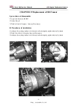
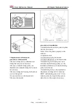
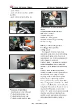
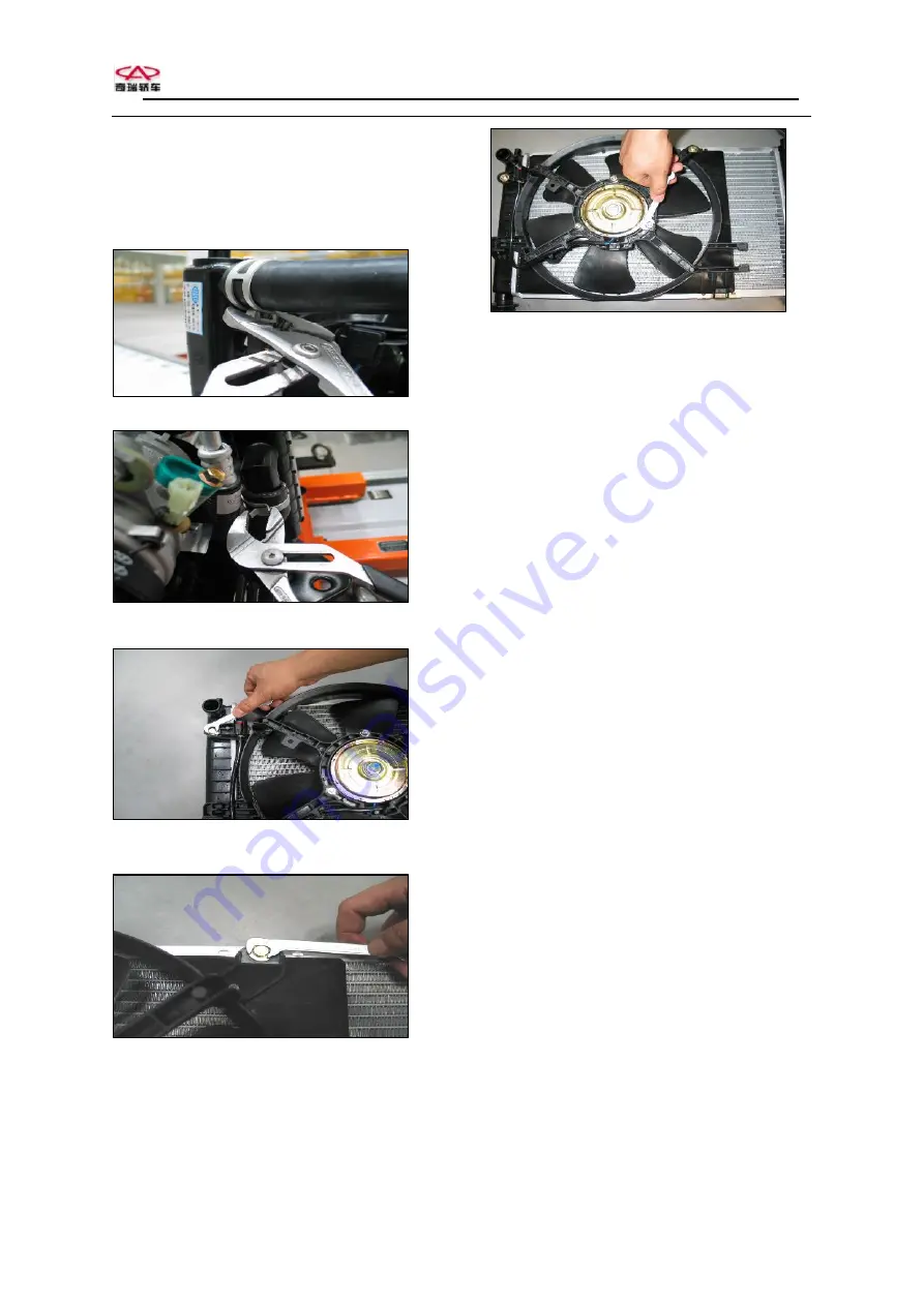
Loosen 2 bolts:
Loosen wire harness and take out fan
assembly
Loosen 4 bolts and pull out the fan

Procedures of installation

1 Install radiator to lower bracket.
3 Connect radiator upper hose.
4 Connect radiator lower hose.
5 Connect coolant overflow hose.

Pay attention to the notices relating to
fastener.
6 Install radiator bracket and bolt
Bolt to 6.0—8.0 Nm
7 Install cooling fan.
8 Refill the cooling system.
9 Install air filter and pipe assembly.
10 Check leakage.

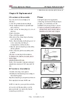
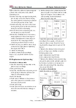
VIII Explanation and operation
1 Cooling system operation
cooling system

Cooling system makes engine keep

appropriate temperature under all working
conditions of engine, when the coolant
temperature is low, the fan operates slowly
to help the engine warm up.
Cooling system is composed of a radiator,
coolant reclaiming system ,cooling fan
thermostat, water pump cover and driving
belt.
Cooling system needs all components
working normally, coolant is pumped from
the radiator by water pump, it will be
recycling in inlet manifold and cylinder
head of engine body through coolant
housing, then it comes back to the radiator,
there, cooling system will make some of the
coolant lead to the heater core from hose for
being heated and unfroze. Reservoir tank is
integrated with radiator, reservoir tank
retrieve the coolant which expand outwards
when the temperature is high and keep
suitable coolant level, along with cooling
and contraction of coolant, coolant is

Summary of Contents for DA465Q-1A2/D

Page 1: ...em 1 Chery Automobile Co Ltd CONTENTS CHAPTER 1 2 CHAPTER 2 5 CHAPTER 3 21 CHAPTER 4 31 CHAPTER 5 34 CHAPTER 6 35 CHAPTER 7 37 CHAPTER 8 39 CHAPTER 9 41 CHAPTER 10 43 CHAPTER 11 45 CHAPTER 12 46 CHAPT...

Page 2: ...275g kwZh gross power NominalRPM 5200r min Idlespeed 850 50r min Emissions Idle speed CO 0 5 HC 100PPm DB11 044 1999 High idle speed CO 0 3 HC 100PPm DB11 044 1999 Mode CO 2 2 g km HC NOX 0 5g km EC...

Page 3: ...gine Metric N m Pulley bolt 95 30 45 Stretching pulley accessories bolt 26 4 Camshaft bracket cover bolt 8 2 Camshaft timing pulley bolt 45 5 Connect rod bearing cap bolt 28 32 Coolant temperature sen...

Page 4: ...o make the engine overloaded if the temperature exceeding the limit or the user uses low viscosity oil such as SAE 5W 30 Regulations C Conventional engine oil NT New Technological oil Classification o...

Page 5: ...ding to the following steps You shall fix the pressure gauge in spark plug hole while the engine working along with the starter you should make the testing cylinders finish 4 compression strokes at le...

Page 6: ...in You should try to make sure frequency of the noise 1 Main bearing noise Noise results from main bearing damage or wear is just like the sound of thud or knocking it happens once every circle that t...

Page 7: ...o much clearance between piston and cylinder liner when the engine is cold sound of slaping is much louder The following circumstance can lead to piston noise l Piston pin wear or too loose l Piston p...

Page 8: ...l Lubrication of valve train is not good or oil pressure is too low l The clearance of valve stem and valve guide pipe is too big l Valve guide pipe wear l Push rod wear l Valve rocker wear l Bolt of...

Page 9: ...of 10 15 km h this kind of noise sounds just like ticktack the following condition can result in this kind of noise l Valve end or Valve rocker gasket wear l Clearance of valve stem and valve guide i...

Page 10: ...ormal noise diagnosis of engine Symptom Cause of malfunction Troubleshooting There is some knocking sound while starting but only continue several seconds Oil viscosity is not suitable Use suitable oi...

Page 11: ...f necessary l Calibrate location of connecting rod l Check connecting rod replace if necessary l Clearance of piston and cylinder liner is not enough l Bore cylinder install new piston l Adjust loosen...

Page 12: ...e belt or pulley rotate every circle l It usually happens in cold and damp morning l Sprinkle some water on the drive belt for confirmation the noise should stop immediately 1 Check to see whether or...

Page 13: ...multi rib driving belt result from driving belt slipping l Blocking or sliding phenomenon of A C system compressor connecting throttle happens when driving belt is overloaded there is some noise 1 Ch...

Page 14: ...g belt rotate every one circle 1 Check to see whether or not there is any severe hollowness Is there any severe hollowness exceeding 1 3 depth of the belt rib To step2 System normal 2 Clean belt pulle...

Page 15: ...cket if necessary Is the maintenance completed System normal 9 Diagnosis of driving belt out of position Step Operation Yes No Definition The following circumstances may result in driving belt out of...

Page 16: ...heck to see whether or not the tensioner of driving belt works normally Is the operation of tensioner of driving belt normal or not To step12 12 Replace the tensioner of driving belt see Replacement o...

Page 17: ...s any abnormal noise 3 Check to see whether or not the oil pressure of engine is suitable 4 Check to see whether or not the oil consumption is too much 5 Check to see whether or not the coolant consum...

Page 18: ...once every flash that is the rotational speed of camshaft 3 Check the following circumstance if the noise is the same as the frequency of camshaft rotational speed l Valve train missing or loose l Va...

Page 19: ...he purpose of inspection not for measurement The engine must be turned off at least 2 minutes before checking oil level it may be the cause of manufacturing tolerance if you add enough oil but the lev...

Page 20: ...with suitable viscosity according to estimated temperature Please use new oil if the old one being diluted Oil pump wear or too dirty clean or replace the oil pump Oil filter is blocked Please replace...

Page 21: ...inutes check to see if there are some leaking drops 3 Identify classification of leakage and possible positions 4 Check the suspicious position with eyes use a mirror if necessary 5 Check the joint or...

Page 22: ...suspicious positions with eyes check the position not easy to see with the help of a mirror 2 6 See the possibilities of leakage for reference if necessary 3 Possibilities of leakage Check vehicle to...

Page 23: ...Chery QQ Service Manual 465 Engine Mechanical System 23 Chery Automobile Co Ltd II Cylinder head...

Page 24: ...4 bowl shape plug 5 cylinder head gasket 6 locating bush 7 bolt 8 valve chamber cover 9 baffle 10 gasket 11 screw 12 gasket 13 gasket assy 14 screw 15 oil filler cap 16 spark 17 distributor built up c...

Page 25: ...3 bowl shape plug 4 plug 5 plug 6 oil pressure sensor 7 bolt 8 bolt 9 bolt 10 washer 11 nut 12 locating bush 13 Water jacket cover 14 Water jacket gasket 15 screw 16 timing bracket 17 upper baffle 18...

Page 26: ...pin 4 piston pin lock ring 5 connecting rod 6 nut 7 connecting rod bearing shell 8 crankshaft 9 main bearing shell 10 crankshaft thrust washer 11 crankshaft front oil seal 12 shield ring 13 crankshaft...

Page 27: ...td V Camshaft valve and rocker 1 camshaft 2 cup ring seal 3 camshaft thrust baffle 4 screw 5 valve rocker shaft 6 screw 7 valve rocker 8 spring 9 adjusting screw 10 nut 11 intake valve 12 exhaust valv...

Page 28: ...ngine Mechanical System 25 Chery Automobile Co Ltd VI Oil pan 1 oil pan assembly 2 oil pan gasket 3 screw 4 oil drain plug 5 gasket 6 oil strainer 7 rubber ring 8 screw 9 oil dipstick guide 10 oil dip...

Page 29: ...y VII Timing belt outside cover and inside cover assembly 1 timing belt inside cover assembly 2 outer cap 3 rubber pad 4 flat rubber ring 5 rubber ring 6 liner 7 screw 8 screw 9 sponge gasket 10 camsh...

Page 30: ...Chery QQ Service Manual 465 Engine Mechanical System 2 Chery Automobile Co Ltd spring 18 screw 19 gasket 20 washer VIII Engine identification Engine No...

Page 31: ...abilized box 4 Pull the throttle bracing wire out of intake pipe assembly that is to say take the throttle bracing wire off the intake pipe bracket by means of loosening the ball inserter with circlip...

Page 32: ...ead 2 Position fix and installation must be accurate 3 Connect warm blow hose and vacuum valve with intake and intake manifold 4 Reconnect fuel pipe after making mark 5 Connect throttle position senso...

Page 33: ...anifold 4 Lower the vehicle remove protective shield of exhaust pipe 5 Loosen nut of exhaust manifold 6 Disconnect exhaust manifold and gasket II Procedures of installation 1 Connect exhaust manifold...

Page 34: ...rocedures of disassemble 1 Take off venting hose between throttle body and camshaft bracket cover 2 Loosen camshaft cover bolt in requested order 3 Take off camshaft cover II Procedures of installatio...

Page 35: ...mark of camshaft timing belt pulley and another dot on belt rear cover Run belt pulley to align dot and dot 3 There is a dot on belt rear cover Run crankshaft to align dot and dot 4 Two timing belt p...

Page 36: ...over of coolant reservoir 5 Remove low pressure hose of radiator and collect the coolant 6 Remove all hoses and cables which connect the cylinder head and intake manifold 7 Remove ignition coil 8 Disc...

Page 37: ...ee relevant content of article 6 3 18 Install air filter and intake hose then connect temperature sensor to harness 19 Connect negative pole cable of battery Chapter 9 Replacement of Sealing Washer of...

Page 38: ...20 0 050 mm intake and exhaust 0 030 and 0 060 mm you should enlarge the hole in order that you can install the valve of much larger size 5 Check the concentricity of maximal ring and minimal ring of...

Page 39: ...taper rymer to cut 3 times as shown in figure First cut at a angle of 15 Then 75 and then 45 to create ideal touch width 2 Angle of exhaust valve seat 3 Intake valve seat cutting sequence is the same...

Page 40: ...ing rod from piston 10 Measure the clearance between piston and cylinder standard 0 040 0 050 mm Notice It is necessary to prepare enlarged standard sized piston of 0 25 mm and 0 50 mm II Procedures o...

Page 41: ...ean the smooth surface of piston get rid of the grease remained in pin hole and fillisters with suitable scraper Check and measure 1 Check stem of fillisters of the piston or skirt of the piston to se...

Page 42: ...t oil flow out 6 Remove oil pressure indication switch 7 Remove exhaust pipe 8 Remove oil pan 9 Take suction oil pipe of oil pump away 10 Remove the oil pump by means of loosening the bolt of oil pump...

Page 43: ...ump body Shown as blow 2 You should use new sealing gasket when installing the oil pump to the crankcase You should smear the HZ 1213 oilproof silicon fluid sealant The surface should be cleaned befor...

Page 44: ...il seal be careful of installation II Procedures of installation 1 Install new rear oil seal of crankshaft Attention Smear Silicon oil on the sealing surface of new sealing washer then fix it on the s...

Page 45: ...eck to see whether or not there are some defects such as scoring unevenness or others default in the journal III Measurement 1 Check the flatness of crankshaft according to the following methods 2 Lif...

Page 46: ...ct crankshaft end face 3 Move the crankshaft along its direction with a screwdriver pay attention to the readings of dial gauge the regulated clearance is 0 13 0 28mm 4 Install connecting rod to crank...

Page 47: ...he stones it is not good to make the polishing too smooth it only needs slight smoothness for helpful lubrication cylinder after grinding you use rough particles stones first then use fine particles P...

Page 48: ...en oil cleaner with SST 2 Collect the oil 3 Check oil level of engine tune up if necessary II Procedures of installation 1 Lubricate the sealing washer of oil cleaner with oil slightly tighten the bol...

Page 49: ...ng to the engine wing and hurting the user who remove the cap Notice It must be sure that you should use regulated coolant if you don t use regulated brand of coolant time of replacing the engine cool...

Page 50: ...m and minimum mark of the reservoir tank continue to add until it is up to the standard 4 Install reservoir tank cap make sure that the arrow on it is showing no difference with the direction of coola...

Page 51: ...igning the hose mark 2 Connect vent hose to the radiator 3 Connect vent hose and engine cooling manifold 4 Refill the cooling system see the illustrations IV Replacement of cooling fan procedures of d...

Page 52: ...Remove thermostat procedures of installation 1 Install thermostat and new gasket tighten the bolt if necessary Notice Place the gasket properly on the entrance 2 Tighten the bolt 3 Connect hose to th...

Page 53: ...on the crankshaft 6 Install camshaft timing pulley to the camshaft see the installation illustration of camshaft timing pulley for reference 7 Install timing belt see the installation and connection i...

Page 54: ...eep appropriate temperature under all working conditions of engine when the coolant temperature is low the fan operates slowly to help the engine warm up Cooling system is composed of a radiator coola...

Page 55: ...as to the position which relay make the fan running at a high speed and diagnosis under the condition of coolant temperature exceed 95 and 102 you can see electric system of engine 5 Explanation of co...

Reviews: