background image


USER’S MANUAL, TR7240 TX/RX 


CHECKPOINT SYSTEMS, INC. CONFIDENTIAL AND PROPRIETARY INFORMATION, FOR INTERNAL USE ONLY 

Document No.  


Rev. 00 

Page 8 of 11 

6.0


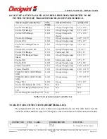
LIST OF ANTENNAS AND CONTROLLER BOXES PERMITED TO BE 
FITTER WITH THE TR4240/TR7240 TRANSCEIVER MODULE. 

Antenna Type/Controller Box 

Aisle 
Width 

Antenna Structure 

Antenna Size 

Evolve P10 iRange 

7.5 ft 

2-loop/3-loop/o-loop 

67” x 19.5” 

Evolve P20 iRange 

6.0 ft 

2-loop/3-loop/o-loop 

67” x 12.5” 

Evolve P20S iRange 

6.0 ft 

2-loop/3-loop with 
shield 

67” x 12.5” 

Evolve G10 iRange 

7.5 ft 

2-loop/3-loop/o-loop 

64.5” x 19.5” 

Evolve G30 

6.0 ft 

2-loop/3-loop/o-loop 

59” x 10” 

Evolve G35 iRange/Classic 
Style 

6.0 ft 

2-loop/3-loop/o-loop 

59” x 10” 

Evolve E10 2.0 ANT RF 

6.5 ft 

2-loop/3-loop/o-loop 

59” x17” 

Evolve F10 iRange 

6.5 ft 

Ferrite core flat 

60” x 8” 

Evolve P30 iRange/Classic 
Street 

6.0 ft 

2-loop/3-loop/o-loop 

60” x 13”


Evolve S10 

6.0 ft 

Ferrite core round 

67” x 5” 

Evolve W10 

6.0 ft 

2-loop/3-loop/o-loop 

67” x 20” 

Classic Trend/PX 

6.5 ft 

2-loop/3-loop/o-loop 

66.5” x 19.5” 

Classic Plus/QX 

5.0 ft 

2-loop/3-loop/o-loop 

66.5” x 12.5” 

EVOLVE IR C10 INTERNAL 
MTG 

6.0 ft 

2-loop/o-loop 

17.5” x 27.5” 

EVOLVE IR C10 EXT/WALL 
MTG 

6.0 ft 

2-loop/o-loop 

17.5” x 27.5” 

Classic N10 

4.0 ft 

2-loop 

32” x 6.3” 

Evolve S10 Remote Elec Ctrl 

N/A 

N/A 

N/A 

Evolve F10 iRange Remote Elec 
Ctrl 

N/A 

N/A 

N/A 

Evolve iRange Remote Elec Ctrl  N/A 

N/A 

N/A 

Table 2: List of antennas and controller box


7.0


12B

MAIN PCB CONNECTIONS (PERIPHERAL I/O) 

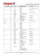
The peripheral I/O will be used to control various peripheral devices. The table below lists the 
connector number and their respective description. These connectors are located on the main board. 


CONNECTOR 

PIN # 

LABEL 

PIN DESCRIPTION 

FUNCTION 

J2 


TX1 A 


TX1 

Ground 

Pri. 2-Loop or PAB via coupler 

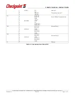
Summary of Contents for TR4240

Page 1: ...t Systems to the user This drawing and or technical information is the property of Checkpoint Systems and is loaned f or mutual a s s is t a n c e t o b e re t u rn e d wh e n it s p u rp o s e h a s b e e n s e r v e d THIS DRAWING AND OR TECHNICAL INFORMATION IS THE P R O P E R T Y O F C H E C K P O I N T S Y S T E M S I N C TR4240 TR7240 TRANSCEIVER REVISIONS REVISIONS REV DESCRIPTION DATE ENGI...

Page 2: ...egulatory Compliance Statement This device complies with the Industry Canada license exempt RSS standard s Operation is subject to the following two conditions 1 This device may not cause interference and 2 This device must accept any interference including interference that may cause undesired operation of the device Le fonctionnement de l appareil est soumis aux deux conditions suivantes 1 Cet a...

Page 3: ...rformance which may include intermittent decreases in detection and or intermittent increases in alarm activity However there is no guarantee that interference will not occur in a particular installation If this equipment experiences frequent interference from external sources or does cause harmful interference to radio communications reception which can be determined by turning the equipment off ...

Page 4: ... 2009 and affects all companies producing importing using or placing products on the European market The aim of the REACH regulation is to ensure a high level of protection of human health and the environment from chemical substances Checkpoint Systems substances management system follows and complies with the current revision of the REACH Regulation on the substances as identified by ECHA Europea...

Page 5: ... 3 Memory 7 3 4 Environmental 7 4 0 POWER SUPPLY REQUIREMENTS 7 5 0 Device Labeling 7 6 0 list of Antennas and controller box to be fitter with the TR4240 TR7240 TRANSCEIVER module 8 7 0 12BMain PCB Connections Peripheral I O 8 8 0 Communications Board I O 10 LIST OF FIGURES NO FIGURES INCLUDED LIST OF TABLES TABLE 1 POWER CONNECTOR PIN ASSIGNMENTS 7 TABLE 2 LIST OF ANTENNAS AND CONTROLLER BOX 8 T...

Page 6: ...ply The antenna is constructed with two canceling loop designs consisting of a 2 Loop a 3 Loop and a single Loop which is a shorted turn contributing to far field EM cancellation The Primary Electronics detects targets in the field of the primary antenna in which it is mounted The TR4240 TR7240 PCB integrates both the processing logic controller consisting of a Blackfin DSP and a FPGA and the anal...

Page 7: ... SIGNAL 1 24V RTN 2 GND 3 24V Table 1 Power Connector Pin Assignments The input 24V is converted to 12V 5V 3 3V 2 5V and 1 2V through DC DC converters integrated within the PCB circuitry Both switch mode and linear regulators are used 5 0 DEVICE LABELING The TR4240 TR7240 modules have been labeled with their own FCC ID number and if the FCC ID is not visible when the module is installed inside ano...

Page 8: ...ite core flat 60 x 8 Evolve P30 iRange Classic Street 6 0 ft 2 loop 3 loop o loop 60 x 13 Evolve S10 6 0 ft Ferrite core round 67 x 5 Evolve W10 6 0 ft 2 loop 3 loop o loop 67 x 20 Classic Trend PX 6 5 ft 2 loop 3 loop o loop 66 5 x 19 5 Classic Plus QX 5 0 ft 2 loop 3 loop o loop 66 5 x 12 5 EVOLVE IR C10 INTERNAL MTG 6 0 ft 2 loop o loop 17 5 x 27 5 EVOLVE IR C10 EXT WALL MTG 6 0 ft 2 loop o loo...

Page 9: ...estal Main Power 2 Gnd 3 24v 24 VDC J20 J22 1 Rx A RS485 A IPC 2 Rx B RS485 B 3 GND Ground 4 SYNC SYNC A SYNC 5 SYNC SYNC B 6 GND Ground 7 Tx A RS485 A IPC 8 Tx B RS485 B J41 1 RLY CNT Counter External Counter 2 RLY CNT Counter Ground Return J54 1 24VDC 2 LTS2 SAB Lights SAB Lights 3 LTS PAB SAB Lights Return 4 LTS PAB Lights PAB Lights 5 SND2 SAB Sound Return SAB Sounder 6 SND2 SAB Sound J39 1 LT...

Page 10: ... Document No Rev 00 Page 10 of 11 Table 3 Main PCB Connections 8 0 COMMUNICATIONS BOARD I O CONNECTOR PIN LABEL PIN DESCRIPTION FUNCTION J72 1 PEOPLE CTR RS 485 VisiPlus 2 GND 3 RS 485 4 24VDC J11 1 KEY1 Key Switch 1 2 KEY1 3 INTLK1 NC 4 NC 5 INTLK1 Deactivation Interlock 1 6 INTLK1 J54 1 KEY2 Key Switch 2 2 KEY2 ...

Page 11: ... 2 4 NC 5 INTLK2 Deactivation Interlock 2 6 INTLK2 J51 1 RS232 Rx 2 RS232 Tx Evolve Modem Communications 3 GND 4 5VDC 5 MODEM GND 6 NC 7 RS232 CTS 8 RS232 RTS J44 1 RLY1 NC External Relay 1 2 RLY1 NC 3 EXT RLY GND 4 RLY1 NO 5 RLY1 NO 6 GND J45 1 RLY2 NC 2 RLY2 NC External Relay 2 3 EXT RLY GND 4 RLY2 NO 5 RLY2 NO 6 GND J1 1 Ethernet Table 4 Communications Board I O ...

Reviews: