Chauvet Slim Par Pro TRI User Manual Download Page 16

 
5. Appendix 

16 

6/24/2013 11:35 AM  

DMX Primer 


There are 512 channels in a DMX connection. A fixture capable of receiving DMX will require one 
or a number of sequential channels. The user must assign a starting address on the fixture that 
indicates the first channel reserved in the controller. There are many different types of DMX 
controllable fixtures and they all may vary in the total number of channels required. Choosing a 
start address should be planned in advance. Channels should never overlap. If they do, this will 
result in erratic operation of the fixtures whose starting address is set incorrectly. You can 
however, control multiple fixtures of the same type using the same starting address as long as the 
intended result is that of unison movement or operation. In other words, the fixtures will all 
respond exactly the same.  


DMX fixtures are designed to receive data through a daisy chain. A daisy chain connection is 
where the DATA OUT of one fixture connects to the DATA IN of the next fixture. The order in 
which the fixtures are connected is not important and has no effect on how a controller 
communicates to each fixture. Use an order that provides for the easiest and most direct cabling. 
Connect fixtures using shielded two conductor twisted pair DMX data cable with three pin XLR 
male to female connectors. The shield connection is pin 1, while pin 2 is Data Negative (S-) and 
pin 3 is Data positive (S+). 


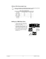
Fixture Linking (Daisy Chain) 


You will need a daisy chain to run light shows of one or more fixtures using a DMX controller or to 
run synchronized shows on two or more fixtures set to a master/slave operating mode. The 
combined number of channels required by all the fixtures on a daisy chain determines the number 
of fixtures the data link can support.  


To comply with the EIA-485 standard, do not connect more than 32 fixtures on one daisy 
chain. Connecting more than 32 fixtures on one daisy chain without the use of a DMX 
optically-isolated splitter may result in deterioration of the digital DMX signal.  


Maximum recommended cable distance: 500 m (1640 ft)  
Maximum recommended number of fixtures on a daisy chain: 32 


Data Cabling 


To link fixtures together you must obtain data cables. You can purchase CHAUVET® certified 
DMX cables directly from a dealer/distributor or construct your own cable. If you choose to create 
your own cable please use data-grade cables that can carry a high quality signal and are less 
prone to electromagnetic interference. 


DMX Data Cable 


Use a Belden© 9841 or equivalent cable which meets the specifications for EIA RS-485 
applications. Standard microphone cables cannot transmit DMX data reliably over long distances. 
The cable must have the following characteristics: 


Type: 

shielded, 2-conductor twisted pair 

Maximum capacitance between conductors: 

30 pF/ft 

Maximum capacitance between conductor and shield: 

55 pF/ft 

Maximum resistance: 

20 ohms/1000 ft 

Nominal impedance: 

100 ~ 140 ohms 


Summary of Contents for Slim Par Pro TRI

Page 1: ...User Manual ...

Page 2: ...DUCTION 5 PRODUCT OVERVIEW 6 3 SETUP 7 AC POWER 7 Power Linking 7 MOUNTING 8 Orientation 8 Rigging 8 4 OPERATING INSTRUCTIONS 9 CONFIGURING THE STARTING ADDRESS 9 CONTROL PANEL FUNCTIONS 9 MENU MAP 10 OPERATION 11 DMX Operation 11 Master Slave Mode 11 STANDALONE 12 Automatic 12 Static Color 12 Custom Static Color 12 DMX CHANNEL VALUES 13 3 CH Mode 13 4 CH Mode 13 9 CH Mode 14 5 APPENDIX 15 GENERAL...

Page 3: ...certain types of information from the regular text CONVENTION MEANING 10 A DIP switch to be configured Menu A key to be pressed on the fixture s control panel 1 512 A range of values 50 60 A set of values of which only one can be chosen Settings A menu option not to be modified for example showing the operating mode current status MENU Settings A sequence of menu options to be followed ON A value ...

Page 4: ...ect from power source before servicing or replacing fuse and be sure to replace with same fuse source Secure fixture to fastening device using a safety chain Maximum ambient temperature Ta is 104 F 40 C Do not operate fixture at temperatures higher than this In the event of a serious operating problem stop using the unit immediately Never try to repair the unit by yourself Repairs carried out by u...

Page 5: ...2 Introduction 5 6 24 2013 11 35 AM 2 INTRODUCTION ...

Page 6: ...2 Introduction 6 6 24 2013 11 35 AM Product Overview Power In DMX Out Bracket Adjustment Knob Fuseholder Control Panel LED Display DMX In Safety Power Out Hanging Bracket Bracket Adjustment Knob ...

Page 7: ...sed only as a 0 to 100 switch Always connect the fixture to a circuit with a suitable electrical ground Power Linking This fixture contains power linking via the Edison outlet located in front of the power input cable Please see the diagram below for further explanation The maximum quantity of SlimPAR Pro TRI that may be linked is 15 The power linking shown in this document is for the CHAUVET Nort...

Page 8: ...onsider routine maintenance and control panel access Please see the following notes on installation If the power link out is intended to be used with multiple fixture take into account the length of each power cable and mount the fixtures close enough to one another to accommodate for this When aiming the fixtures you may use the bracket adjustment knob s Loosen the knob s adjust to the desired an...

Page 9: ...e using DMX we recommend reading the DMX Primer section in the Appendix Control Panel Functions Access control panel functions using the four buttons located directly underneath the LED display on the included wired remote BUTTON FUNCTION MENU Used to scroll through the current operating mode as well as back out of the current menu option ENTER Used to select a move to the right in the menu map an...

Page 10: ...Dimming Curve dIM OFF Dimming curve off dIM1 Dimming curve dim 1 dIM2 Dimming curve dim 2 dIM3 Dimming curve dim 3 Static Color C C 01 Red C 02 Green C 03 Blue C 04 Cyan C 05 Magenta C 06 Yellow C 07 White Custom Static Color U R000 R255 Combine red green and blue to create a custom static color G000 G255 b000 b255 S000 S020 Strobe speed 000 no strobe Auto Program P P 1 P 5 Program selection S000 ...

Page 11: ...ppears on the LED screen PeRS 3 Press ENTER 4 Using UP DOWN select the desired personality 9 CH 4 CH 3 CH 5 Press ENTER 6 Press MENU until AddR appears on the LED screen 7 Press ENTER 8 Using UP DOWN select the desired DMX starting address d001 d512 9 Press ENTER Only connect 32 fixtures to a single DMX daisy chain Master Slave Mode This mode allows a single unit the master to operate in one of th...

Page 12: ...ions below for details on entering this mode 1 Remove any DMX controller from the fixture 2 Press MENU to select Static Color mode C 3 Press ENTER 4 Using UP DOWN select one of the seven presets 5 Press ENTER Custom Static Color This fixture has the ability to accept custom static color settings Access this via the control panel Please see the instructions below for further explanation 1 Press MEN...

Page 13: ... Channel Values 3 CH Mode CHANNEL VALUE FUNCTION 1 000 ó 255 Red 0 100 2 000 ó 255 Green 0 100 3 000 ó 255 Blue 0 100 4 CH Mode CHANNEL VALUE FUNCTION 1 000 ó 255 Master Dimmer 0 100 2 000 ó 255 Red 0 100 3 000 ó 255 Green 0 100 4 000 ó 255 Blue 0 100 ...

Page 14: ...0 Green 0 Blue 100 Red 100 Green 0 Blue 100 0 Red 100 Green 100 0 Blue 0 100 Red 100 0 Green 100 0 Blue 100 Red 100 Green 100 Blue 100 White 1 3 200 K White 2 3 400 K White 3 4 200 K White 4 4 900 K White 5 5 600 K White 6 5 900 K White 7 6 500 K White 8 7 200 K White 9 8 000 K White 10 8 500 K White 11 10 000 K 6 000 ó 009 010 ó 255 Strobe No function 0 20 Hz slow fast 7 000 ó 051 052 ó 101 102 ó...

Page 15: ...ng Damaged DMX cables Check DMX cables Wrong polarity settings on the controller Check polarity switch settings on the controller Loose DMX cables Check cable connections Faulty DMX interface Replace DMX input Faulty Main PCB Replace Main PCB Loss of signal Non DMX cables Use only DMX compatible cables Bouncing signals Install terminator as suggested Long cable Low level signal Install amplifier r...

Page 16: ...e pin 2 is Data Negative S and pin 3 is Data positive S Fixture Linking Daisy Chain You will need a daisy chain to run light shows of one or more fixtures using a DMX controller or to run synchronized shows on two or more fixtures set to a master slave operating mode The combined number of channels required by all the fixtures on a daisy chain determines the number of fixtures the data link can su...

Page 17: ...o read the data on the channel indicated by the start address For example a fixture that uses six DMX channels and was addressed to start on DMX channel 100 would read data from channels 100 101 102 103 104 and 105 Choose start addresses so that the channels used do not overlap and note the start address selected for future reference If this is your first time addressing a fixture using the DMX co...

Page 18: ...n 4 Not used Pin 5 Setting up a DMX Daisy Chain 1 Connect the male 3 pin connector side of the DMX cable to the output female 3 pin connector of the controller 2 Connect the end of the cable coming from the controller which will have a female 3 pin connector to the input connector of the next fixture consisting of a male 3 pin connector 3 Then proceed to connect from the output as stated above to ...

Page 19: ... 20 days Clean the fixture at least every 30 60 days Always dry the parts carefully after cleaning them Never spin a fan using compressed air Returns Procedure Returned merchandise must be sent prepaid and in the original packing call tags will not be issued Package must be clearly labeled with a Return Merchandize Authorization Number RMA Products returned without the RMA will be refused Call CHA...

Page 20: ...F 2 A 250 V LIGHT SOURCE Type Tri color LED red green blue Quantity 18 Rating 3 W 350 mA x 3 50 000 hrs PHOTO OPTIC Lux 1 980 2 m Beam angle 21 Field angle 42 INDOOR OUTDOOR Rating For indoor use only THERMAL Maximum ambient temperature 104 F 40 C CONTROL PROGRAMMING Data input locking 3 pin XLR male socket Data output locking 3 pin XLR female socket Data pin configuration pin 1 shield pin 2 pin 3...

Page 21: ...ation CHAUVET 5200 NW 108 th Ave Sunrise FL 33351 voice 954 577 4455 fax 954 929 5560 toll free 800 762 1084 Technical Support CHAUVET 5200 NW 108 th Ave Sunrise FL 33351 voice 954 577 4455 Press 4 fax 954 929 5560 Attention Service World Wide Web www chauvetlighting com ...

Reviews: