Chatsworth Products RIM-600 User Manual Download Page 82

RIM-600  Manual

82

If you double-click on an item in the Environmental or IP Alarm box, all of the listed items will 
become selected and/or deselected. Last, select a time frame to perform the query and click 

View

.  

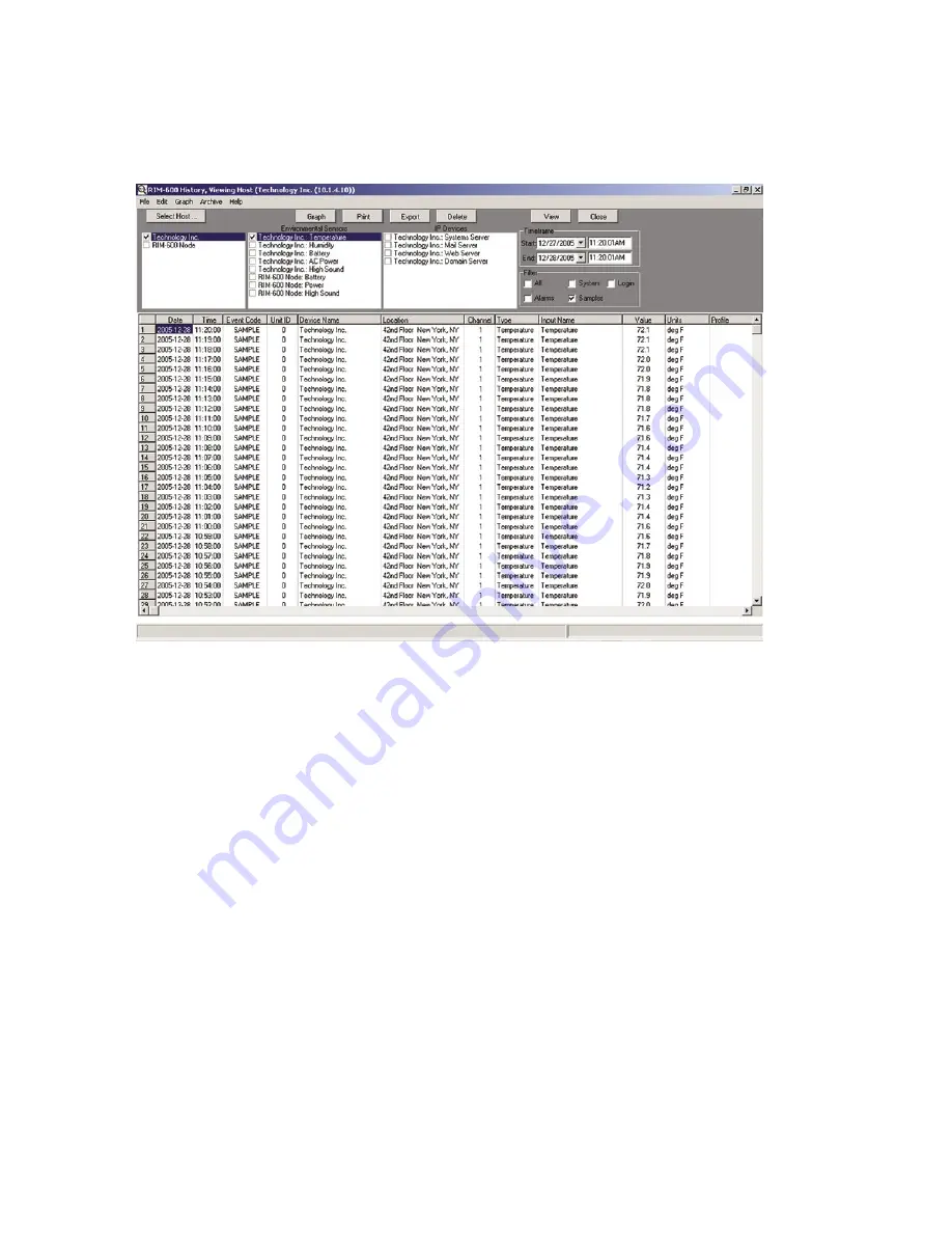
The selected data will now be displayed.  See sample screen below:

Figure 56: History Viewer

Graphing

Graphing data is possible when the selected query contains only Samples.
If you click on the

 Graph

 button, all of the points in the query will be displayed as a line graph. 

There are also options (from the

 Graph

 menu above) to format and display the data as a bar or area 

graph. You can have up to eight items displayed on the graph at once. To view different parts of 
the graph use the arrows on the bottom and sides to adjust the position. A graph can be printed by 
clicking the

 Print

 button at the top of the screen. You can copy the graph to the Windows clipboard 

by clicking the

 Copy

 button. This allows you to paste the graph into other applications. The

 Zoom 

In

 and

 Zoom Out

 buttons let you view the data with more or less detail. The

 Reset

 button restores 

the original view of the graph. When finished, click the

 Close

 button to return to the grid.

Printing Data

You can print the data viewed in the grid by clicking the

 Print

 button.  Printing defaults to an Arial 

5 pt. font in order to fit one line of data across one line of an 8.5" x 11" sheet of paper printed in 
landscape mode. You may choose different fonts and type sizes.

Exporting Data

The

 Export

 button allows you to save the queried data in the grid to a file format which can be 

easily imported into other applications.  Options include the ability to save the file in CSV format, 
formatted text (prn), and tab delimited (txt) format.  Note:  The exported data will represent 

only


what you’ve selected to query.

82

Summary of Contents for RIM-600

Page 1: ...9 techsupport chatsworth com www chatsworth com 2006 Chatsworth Products Inc All rights reserved CPI and MegaFrame are registered trademarks and TeraFrame is a trademark of Chatsworth Products Inc All...

Page 2: ...de by other manufacturers and referred to in this manual will not affect the applicability of the information in this manual Copyright 2006 by Chatsworth Products Inc First Edition version 1 04 Januar...

Page 3: ...supply cord must be used in accordance with applicable UL CSA EN IEC standards and must meet the conductor size and length terms of the above mentioned standards All RIM 600 components Host Node Power...

Page 4: ...lling area The applicable certification jack USOC for this equipment is RJ11C The facility interface code FIC for this equipment is 02LS2 A compliant telephone cord and modular plug are provided with...

Page 5: ...ply with this law you must enter the following information into your RIM 600 Date and Time as described in the Unit Properties section of the Software Manual Name and telephone number to identify the...

Page 6: ...yright 1999 2000 2001 2002 Greg Roelofs Portions relating to gdttf c copyright 1999 2000 2001 2002 John Ellson ellson lucent com Portions relating to gdft c copyright 2001 2002 John Ellson ellson luce...

Page 7: ...OBLIGATION UNDER THIS WARRANTY IS LIMITED TO REPAIR OR REPLACEMENT OF THE PRODUCT AT THE WARRANTOR S OPTION AS TO REPAIR OR REPLACEMENT IN NO EVENT SHALL WARRANTORS BE LIABLE OR RESPONSIBLE FOR PAYMEN...

Page 8: ...a CPI customer service representative This number must appear clearly and promi nently on all shipping containers Containers without the labels will not be accepted Products returned for warranty repa...

Page 9: ...is Manual 20 HOST INSTALLATION and CONFIGURATION 20 Physical Description 20 Front Panel Layout 20 Serial Port 20 RJ 45 10 100BASE T Ethernet Port 20 Phone Jack 20 Sensor Inputs 21 Sensor Input LEDs 21...

Page 10: ...tion 34 Wall Mount Installation 34 Tabletop Installation 35 Connecting Sensors 35 Network Configuration 36 Local Configuration Definitions 37 Node Specifications 38 Operating Specifications 38 Communi...

Page 11: ...for the RIM 600 Host 45 Adding a Node 46 Deleting a Node 47 Changing Host Network Settings using ConsoleView 47 Setting the Unit Properties for the Node 47 Sample Application 48 Changing Node Network...

Page 12: ...ing 67 Reconnecting 67 Recording and Uploading Voice Messages 67 Recording Voice Messages 67 Holiday Setup 69 Alarm Message Pop Ups 70 Activating Alarm Pop Ups 70 Enabling Custom Pop Up Messages 70 Se...

Page 13: ...mware 84 Chapter 3 Operation 85 Alarm Delivery and Acknowledgment 85 Alarm Acknowledgment 85 Alarm Delivery Logic 86 Sample Alarm Messages 86 Sample E mail alarm message 86 Sample Fax message 87 Sampl...

Page 14: ...a Telephone 97 Switching Outlets via Email 97 RIM 600 PowerGate Specifications 98 Operating Specifications 98 Chapter 6 PowerGate2 99 Physical Description 99 Front Panel Layout 99 Rear Panel 99 LEDs 9...

Page 15: ...11 001 Room Temperature Sensor with display Fahrenheit 111 Installation Instructions 111 Introduction 111 Package Contents 111 Cabling 111 Mounting 111 Electrical box installation 111 Hidden cable sur...

Page 16: ...late factory default 121 Specifications 121 60031 001 Room Humidity Sensor with display 122 Installation Instructions 122 Introduction 122 Cabling 122 Mounting 122 Electrical box installation 122 Hidd...

Page 17: ...ory default 133 Specifications 133 60051 001 4 20mA Bridge 134 Installation Instructions 134 Introduction 134 Package Contents 134 Wiring the Transducer 134 Cabling 134 Mounting 135 Configuration 135...

Page 18: ...s 143 Introduction 143 Cabling 143 Mounting 143 Configuration 143 Sensor Template factory default 144 Specifications 144 Technical Support for the RIM 600 Sensors 145 Appendix A Weekly Testing Procedu...

Page 19: ...y perform diagnostic tests via Touch Tone commands or e mail And with the RIM 600 PowerGate you can also remotely reboot equipment Features The RIM 600 series of products includes the following key fe...

Page 20: ...igure 1 Front Panel Layout of the RIM 600 Host 1 Serial Port 2 Ethernet port 10 100Base T 3 Phone line 4 Sensor Inputs 8 5 Battery Power Alarm LED 6 AC Power Alarm LED 7 External Microphone Input 8 In...

Page 21: ...Chapter 7 The use of RJ 45 jacks for sensor inputs allows the use of existing structured cabling to connect remote sen sors Since the sensor produces an analog signal it must connect directly to the...

Page 22: ...ch as smoke detectors When an external microphone is connected the internal microphone is disabled Rear Panel The rear panel is where the main power switch is located The main power cord attaches to t...

Page 23: ...included rack mount brackets Follow the steps below 1 Attach rack mount brackets to the sides of the Host unit with a Phillips screwdriver 2 Attach the unit to the equipment rack using two pan head sc...

Page 24: ...performing internal diagnostic tests The unit will also beep once 25 seconds after power is applied When the LEDs stop blinking the unit is fully booted and operational The boot and Power On Self Test...

Page 25: ...umb terminal or terminal emulation software is required to get online and set up the configuration The port is male DTE so you will need to use a null modem cable Terminal communication settings must...

Page 26: ...d Datamodem Enabled SNMP RO community public SNMP RW community private SNMP Agent Enabled Allow remote configuration Disabled Press any key to return to main menu Option 3 will allow you to set all pe...

Page 27: ...t username admin password rim600 This temporary account will unload if any one of the following occurs 1 Any of the Master Administrator accounts is edited 2 A new Master Administrator account is crea...

Page 28: ...at will transfer TCP IP data in and out of your LAN A single LAN that is not connected to other LANs does not require a gateway setting DNS The DNS server is used to translate site names into actual n...

Page 29: ...age depth of discharge Eventually battery replacement will be required to maintain a dependable level of service Replacing the Battery The battery in the Host can be replaced by following the instruct...

Page 30: ...tor with the red wire from the battery Step 8 Using the nut driver remove the four nuts which hold down the battery bracket Remove the bracket and battery Step 9 Install the new battery and replace th...

Page 31: ...ackup Battery 12V 2 9AH Sealed Gel Cell Backup Time 3 5 Hours Ethernet 10 100 Base T 10 100Mbps RS 232 DB9 9600bps DTE Modem 33 6Kbps Fax Group 3 14 4Kbps Voice Processor Yes Internal Monitoring AC Po...

Page 32: ...allows the use of existing structured cabling to connect remote sen sors Microphone The Node unit comes with a built in microphone Directly below the built in mic is a separate jack for connecting an...

Page 33: ...at head screwdriver Installation This section provides information on n Operating environment n Rack wall tabletop installation n Connecting sensors n Replacing the battery Parts Required Phillips DB9...

Page 34: ...ttach the top cover Figure 8 Battery replacement in the Node unit Rack Mount Installation The RIM 600 Node can be rack mounted using the included rack mount brackets Follow the steps below 1 Attach ra...

Page 35: ...available to monitor the following n Temperature n Smoke n Humidity n Security n Water detection n Motion n AC voltage n Alarm contacts from external equipment All RIM 600 sensors connect to the Node...

Page 36: ...control To get online with the RIM 600 Node connect your terminal to the serial port and press RETURN A menu will appear which will guide you through the setup RIM 600 Node Unit Version 4 10 Main Men...

Page 37: ...This is the IP address of the RIM 600 Host that this Node is associated with Node IP Address This is the IP address assigned to the RIM 600 on your network This address is provided by you or your netw...

Page 38: ...h x 7 0 d x 9 6 w Backup Battery 1 6V 3 4AH sealed rechargeable Backup Time 3 5 Hours Ethernet 10 100 Base T 10 100Mbps RS 232 DB9 9600bps DTE Internal Monitoring AC Power Backup Battery Level Sound...

Page 39: ...e RIM 600 Host and Node s Configure the Network settings through the serial port on the front of the units A terminal or terminal emulation program can be used Set the terminal set tings for 9600bps 8...

Page 40: ...re the Node Properties for each Node Configure Input Templates Environmental input programming Templates are used to load user specified defaults each time a new sensor is connected to a Host or Node...

Page 41: ...Add New IP Alarm Enter the information to configure the network device you wish to monitor Be sure to enable the alarm The RIM 600 unit will ping connect to the IP address and port you select about o...

Page 42: ...ible sound card microphone and speakers Windows compatible phone modem and or RS 232 ports Software Installation The RIM 600 ConsoleView Software setup program makes installation quick and easy Make s...

Page 43: ...ted to that Host and all of the environmental inputs connected to these units regardless of proximity to the Host Note Before setting up your Enterprise software you must have locally configured your...

Page 44: ...attempt to connect to your RIM 600 Host A progress bar will show the software retrieving information from the Host Default Username admin Default Password rim600 Note Do not save the default username...

Page 45: ...ce file Custom voice messages can be recorded and uploaded to the Host on the Custom Voice Manager screen The Host Custom Voice message is the first message spoken during a voice call This message sho...

Page 46: ...ing to its location If you would like the unit to synchronize its time on a daily basis enter the IP address of a compatible time serv er Figure 11 Clock settings tab The RIM 600 can be programmed to...

Page 47: ...etwork Settings The first tab is titled Ethernet Settings click the Modify button to bring up the Network Setup screen Figure 13 Host Network Settings NOTE If the Modify button is grey inactive then t...

Page 48: ...d about network traffic generated by Node to Host communication but want to view input values that are no more than 20 minutes old You can enable the Auto Send option and enter an interval of 1200 sec...

Page 49: ...Environmental Inputs Each host or node can have up to 8 external sensors connected The host or node will automatically identify what sensor type is connected to each input To program the environmenta...

Page 50: ...enabled for alarm monitoring If it is disabled the RIM 600 will not send alarm messages A channel can be enabled or disabled based on a 7 day holiday time schedule Schedule Click this button to bring...

Page 51: ...ass Setup screen Figure 19 Alarm Class dropdown menu Custom Voice Click the drop down arrow and select the custom voice message you would like assigned to this sensor channel Voice messages can be rec...

Page 52: ...to program for alarm response New State Select the action you want to have occur On Off Cycle Click the Add button to add this response to the list of current responses click Delete to remove an actio...

Page 53: ...y the RIM 600 The unit is programmed to trip an alarm if the sound level increases by a programmed number of decibels On the High Sound programming screen this parameter is listed as Change in dB The...

Page 54: ...e calls Trouble Alarms The RIM 600 monitors the presence of all connected sensors to insure the reliability of the system When a sensor is removed from a Host or Node for more than a minute a trouble...

Page 55: ...the options under this heading Next expand the Input Templates This will list all of the different sensor types Figure 24 Template Types Right click on each of the sensor names to bring up the indivi...

Page 56: ...ng Or in other words the monitored IP address is dependent upon the Dependency IP address to function Alarm is Enabled Unchecking this box will disable the IP alarm Add to Datalog Click this box to st...

Page 57: ...ed Alarm Class Click the drop down arrow and select the appropriate class for this type of alarm If you prefer you can create your own classes on the Class Setup screen to group certain types of alarm...

Page 58: ...til the dependency device returns to normal e g starts responding to ping connect requests When an IP Alarm s dependency is not responding the status for the IP Alarm will be shown as IP route down It...

Page 59: ...2 Software 59 Figure 28 IP Alarm Flowchart Removing an IP Alarm Expand the IP Alarms and right click on the IP Alarm you wish to remove Choose Delete this IP Alarm and it will be removed Chapter 2 Sof...

Page 60: ...Classes are Diagnostic Temperature Humidity Water Power Other Smoke Security Backup Battery High Sound IP Alarms Figure 29 Setup Classes You can have up to 64 classes in the RIM 600 To add Classes ju...

Page 61: ...e button The Profile should now display in its new location Adding a Profile Right click on Profiles and select Add New Profile The following screen will appear Figure 30 User Profile screen The Name...

Page 62: ...security level is as follows Master System Site Admin Admin User Add user profiles Yes No No Disable user profiles Yes No No Edit unit properties Yes No No Edit e mail settings Yes No No Edit Node pro...

Page 63: ...can only receive information or send commands if they have the proper permissions and Class associations Examples 1 If a User that has no Permissions on a particular Node then the user will not be abl...

Page 64: ...er of Contacts can be changed at any time To move a Contact up or down in the list click and hold the Contact you wish to move and drag it to its new location then release the mouse button The Contact...

Page 65: ...sion 170 will be dialed after the auto attendant answers Numeric Pager Calls The RIM 600 can send alarm messages to numeric pagers It will automatically send its ID tele phone number when dialing to a...

Page 66: ...enable disable specific hours days Alarm Delivery Options There are additional options which appear on the Contact Setup screen depending upon the type of call For alarm delivery you must select eith...

Page 67: ...e to a system restart or other communication related problem You can reconnect to a RIM 600 using the Reconnect command To reconnect to a unit click on File from the main menu and select Reconnect Hig...

Page 68: ...essage click the right arrow Play button Trim off any silence before and after the message to ensure that the voice report flows smoothly Messages can be trimmed by sliding the message position bar an...

Page 69: ...ows you to program recurring or non recurring holidays that you can use with in your schedule programming These schedules are used to enable or disable monitoring of Environmental and IP Alarms and al...

Page 70: ...rm Pop Ups Click on File then Options from the main menu in the ConsoleView Software The following screen will appear Figure 41 Options Screen Within the section titled Alarm Notification click in the...

Page 71: ...rea This window will scroll to accommodate lengthy actions Note that using HTML you can embed web links in the message for more advanced actions To test your HTML code click the Preview button To retu...

Page 72: ...Mail Check Interval SMTP Error messages If your e mail settings are incomplete or incorrect there are some messages that will appear in the Event History log which may be helpful The Invalid Configura...

Page 73: ...dress for your RIM 600 from your internet provider configure the e mail settings for your RIM 600 Host see e mail setup and have Two Way E mail enabled see Host Local Configuration in the Host Install...

Page 74: ...e captured when the RIM 600 receives the e mail request To receive a picture send an e mail message to your RIM 600 Host with the following information To e mail address of your RIM 600 Subject rim600...

Page 75: ...four cameras can be viewed at the same time You can view a single camera by clicking on the video image you want to display If you click again it will return to the quad image You can also capture a...

Page 76: ...lists all cameras programmed into the system The window on the right lists cameras associated with the selected Host or Node To move a single camera to the other window highlight the camera and click...

Page 77: ...e web page can also be password protected You can program most parameters through the web page if the Web Page Programming option is enabled This can be secured with the same permissions options as wi...

Page 78: ...he WebView tab Check the Automatic Refresh box and enter the number in seconds between updates in the Update Every box Figure 51 Web Page Refresh Enabled Remote Web Page The RIM 600 can send a copy of...

Page 79: ...ge To view the remote web page that the RIM 600 uploaded you need to know its web address This address corresponds to the Server name plus the directory plus the file name of the web page It will look...

Page 80: ...ht click menus of the ConsoleView software You can choose to have the graphed data displayed as a line graph or simply show the discrete data points You can also deselect the Automatically Update butt...

Page 81: ...Querying the History Database with HistoryView The HistoryView program allows you to query the entire History database for all RIM 600 units There are filters to select Samples Alarms System messages...

Page 82: ...Print button at the top of the screen You can copy the graph to the Windows clipboard by clicking the Copy button This allows you to paste the graph into other applications The Zoom In and Zoom Out b...

Page 83: ...ull will appear in the status bar along the bottom of the grid A warning message will appear when the database reaches 80 of its capacity To archive the history database select Archive from the main m...

Page 84: ...on updates To check the version of Firmware in your RIM 600 right click on the Hostname and select Version Info The following screen will appear Figure 58 Version Info Screen The RIM 600 unit firmwar...

Reviews: