8
Introduction/Operation
Product Manual - Nomad 830G MP
Preparing the Tank for Use
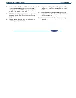
(Refer to Figure 3)
1
Disconnect the trailer from the tow vehicle and use the
drop legs at the front and rear of the trailer to ensure
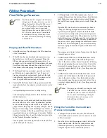
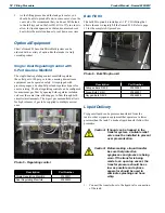
deck is level. This can be accomplished by referencing
the levels mounted at the side and front of the trailer
(see Figure 2)
Figure 2 - Level mounted on trailer
2
If optional regulating manifolds were not included,
connect the proper regulator/regulating manifold to the
liquid cylinder's gas use outlet
3
Connect the proper piping / hoses between the final
line regulator / 6-port gas manifold and the receiving
equipment
4
If empty, fill tank (refer to Fill Procedure on page 13).
5
Close the Road Relief isolation valve (A).
6. Open the Pressure Building isolation valve (B).
7
Open the Economizer circuit (C).
8
Monitor the PB Gauge (D) and wait for the tank to
reach operating pressure.
9
Once the tank has reached operating pressure open the
Gas Use isolation valve (E)
10
When gas delivery is complete, close the Gas Use valve
(E)
Preparing the Tank for Transport
(Refer to Figure 3)
1
Ensure the Gas Use isolation valve (E) is closed.
2
Close valves on the final line regulator or 6-port
manifold
3
Ensure pressure has been relieved from all equipment
lines. Disconnect all hoses and equipment from the final
line regulator or 6-port manifold.
4
Close the Economizer (C) and Pressure Building (B)
valves
5
Open the Vent valve (F) until the tank pressure is at or
below 17 psig.
6. Close the Vent isolation valve.
7
Open the Road Relief isolation valve (A).
8
Connect the Trailer to the towing vehicle referencing
the Felling trailer owner's manual.
9
Raise the drop legs on the front and rear of the trailer.
10
The Nomad 830 MP unit can now be transported on
public roads
Primary Plumbing Circuits
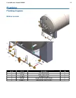
(Refer to Figure 4 on Pg. 10)
Fill
The Nomad 830 MP w/FlexFill
™
Piping has a top and
bottom fill circuit that replaces the top float assembly so the
driver can control the tank pressure while filling the Nomad
MicroBulk System. The fill circuit is a one-piece manifold
(VM-1) consisting of a top fill valve, a bottom fill valve, a fill
check valve (V-1), and a hose drain valve.
The fill line check valve has a service fitting on the inlet
side that provides the sole connection for the liquid delivery
vehicle
The hose drain valve can be used to both purge the fill hose
before filling the tank or to depressurize the fill hose after
filling the tank.
The driver controls the pressure in the vessel during the fill
process by adjusting the flow through the top and bottom fill
valves. Product flowing into the bottom of the tank will raise
the pressure and product flowing into the top of the tank will
lower the pressure. Adjusting each valve properly will allow
the driver to hold a consistent pressure in the tank throughout
the entire delivery
During a first fill, only fill the vessel to 75% full to allow
liquid expansion experienced with a new "hot" tank. Each
fill thereafter can be filled to 100% full. Please refer to
the Installation section of this manual for detailed filling
procedures


