background image

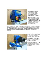
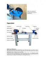
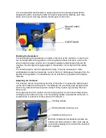
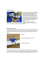
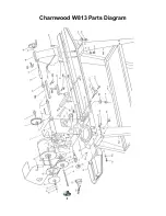
Charnwood W813 Parts List 


No. 

Description 


No. 

Description 

01 

Headstock Casting 


36B 

Tool Rest Post 25mm Diameter 

02 

Drive Centre 1MT 


37B 

Ratchet Handle 

– Tool Rest 

03 

Faceplate 


37C 

Ratchet Handle - Tailstock 

04 

Headstock Spindle 


38 

Tool Rest Extension 

05 

Key 


39 

Tool Rest Body (Banjo) 

06 

Bearing  6205Z 


40A 

Tool Rest Locking Handle 

07 

Bearing  6205Z 


41 

C Ring/ Circlip 

08 

Spring 


42 

Tailstock Cam Hanger 

09 

Pulley Shift Bracket A 


43 

Clamp Plate 

10 

Bearing  6007Z 


44 

M18 Nyloc Hex Nut 

11 

C Ring Circlip 


45 

Tail Centre 1MT 

12 

Pulley Spindle - Right 


46 

Tailstock Spindle 

13 

Drive Belt 


47 

Tailstock Screw 

14 

Pulley Spindle 

– Left 


48 

Tailstock Casting 

15 

C Ring Circlip 


49 

Tailstock Hand Wheel 

16 

Knock Out Bar  


50 

Tailstock Locking Handle 

17 

Screw 


51 

Grub Screw 

18 

Rear Headstock Clamp 


52 

Extension Bed 

19 

Screw 


53 

Hex Socket Screw 

20 

Rack Shaft 


53-1 

Washer 

21 

Speed Change Shaft Assembly 


54-1 

Floorstand Leg (front left / rear right) 

21-1 

Screw 


54-2 

Floorstand Leg (front right / rear left) 

22 

Front Headstock Clamp 


54-3 

Floorstand Top Plate 

23 

Headstock Spanner 32mm 


54-4 

Floorstand Shelf 

24 

Locking Shaft 


55 

Cast Iron Bed 

24-1 

Spring 


56 

Hex Socket Screw 

24-2 

Rotation Lock Handle 


57 

On/Off Switch KJD12 

24-3 

Handle Fixing Screw 


58 

Screw 

25 

Tool Rest Cam Hanger 


60 

Coach Head Bolt 

26 

C Ring/Circlip 


61 

Washer 

27 

Sleeve 


62 

Nut 

28 

Spring 


63 

Power Cable 

29 

Motor Pulley -  Left 


64 

Speed Display (New 

– Inset) 

30 

Motor Pulley - Right 


65 

Speed Sensor 

31 

Screw M5 x 10mm 


66 

Speed Label 

32 

Key 4 x 4 x 85mm 


68 

Switch Housing 

33 

Motor 550W, 240V 


69 

Hand Wheel 

34 

Cover, Drive Belt 


70 

Tool Tray 

35 

Plunge Lock 


36A 

Tool Rest Crossbar 225mm Width 


Summary of Contents for W813

Page 1: ...ATHE OPERATORS MANUAL MODEL W813 Charnwood Cedar Court Walker Road Hilltop Industrial Estate Bardon Hill Leicestershire LE67 1TU Tel 01530 516 926 Fax 01530 516 929 email sales charnwood net website www charnwood net ...

Page 2: ... accident 6 Do not use in dangerous environments Do not use power tools in damp or wet locations or expose them to rain Keep work areas well illuminated 7 Keep children away All visitors should be kept a safe distance from the work area 8 Make workshop childproof Use padlocks master switches and remove starter keys 9 Do not force the machine It will do the job better and be safer at the rate for w...

Page 3: ... tool rest or the bed of the lathe and then start the lathe at its slowest speed When you are certain that that the work is secure and not too out of balance set the lathe to the normal turning speed 4 Always check the rotation speed before switching the lathe on to avoid the risk of starting it whilst it is set to run at too high a speed 5 The speed of the lathe must be adjusted to suit the size ...

Page 4: ...d woodworking enthusiasts Generally lighter weight machines with lower power ratings and smaller tooling capacities Typically only ever used by one person for short periods of time or longer periods of time infrequently Machinery should be well maintained in a clean dry environment such as a home workshop garage or timber shed Expected maximum use of 100 hours annually Please Note Using a product ...

Page 5: ... Bolt on the top plates which fit inside the legs Square up the assembly and tighten all the nuts and bolts Fitting the Lathe to the Stand Lift two people are required for this stage the lathe bed complete with headstock tailstock and tool rest on to the stand Fig 2 Line up the fixing holes in the bed with those in the stand and join the two with the 8 long cap head bolts spring washers and nuts O...

Page 6: ...ck spindle and the tail centre into the tailstock spindle These may be removed by inserting the knock out bar into the other end of the spindle and tapping the centre out It is advisable to put a hand under the centre when knocking it out to prevent the centre from falling to the floor and being damaged Bolt the left hand extension bed to the headstock end of the main bed using 2 fixing screws The...

Page 7: ...nd Stopping Slide up the red switch cover and lift the cover Press the green on button to start the lathe Press the red off button to stop the lathe When the switch cover is down pressing the cover activates the stop button The lathe must be running before you use the speed control To change the speed pull the end of the lever towards you then slowly rotate it to the desired speed The revolutions ...

Page 8: ...ortable to rotate the headstock round to the front 90 degrees clockwise from the spindle turning position The headstock can be locked in any position at 45 degree intervals Adjusting the Tailstock The tailstock can be moved along the bed of the lathe To release the tailstock pull up the silver tailstock locking lever The tailstock can now freely slide along the bed when it is positioned where requ...

Page 9: ...tock has been moved away from the spindle turning position Adjusting the Toolrest The toolrest can be moved along the bed of the lathe To release the toolrest pull up the silver toolrest locking lever The toolrest can now freely slide along the bed when it is positioned where required clamp it firmly in place by pressing the lever firmly down Toolrest Toolrest Height Adjustment Lever Toolrest Lock...

Page 10: ...ll become worn and will need replacing Stop the lathe in the fastest speed and unplug it from the electric supply Use a hex key to undo the grub screw which holds the silver rotating hand wheel onto the spindle Unscrew the rotating hand wheel from the spindle Locate the 4 retaining screws and remove the belt cover Remove the drive belt from the motor pulleys first Install the new belt and then fol...

Page 11: ... of this lathe DC13MT1 A Drill Chuck with 13mm Capacity and an MT1 fitting Used for boring holes from the tailstock end W834 6 Piece High Speed Steel Chisel Set Includes the 6 most commonly used woodturning chisels everything you need for spindle turning ML28 LED Work Lamp If you need better lighting in your workshop this LED light has a magnetic base which can be attached to the headstock or the ...

Page 12: ...elt Motor is running but spindle not turning Broken drive belt Replace drive belt Motor is overheating Too much load on motor Reduce load on motor make shallower cuts Airflow to cooling fan is blocked Remove fan cover and clean grill Spindle rotation slows during cut Excessive depth of cut Make shallower cuts Chisels are dull Sharpen chisels Drive Belt Slipping Check the belt is not frayed Replace...

Page 13: ...with all essential requirements of the directive Signed Dated 23 04 2010 Location Leicestershire Richard Cook Director Please dispose of packaging for the product in a responsible manner It is suitable for recycling Help to protect the environment take the packaging to the local amenity tip and place into the appropriate recycling bin Only for EU countries Do not dispose of electric tools together...

Page 14: ...Charnwood W813 Parts Diagram ...

Page 15: ...ock Locking Handle 17 Screw 51 Grub Screw 18 Rear Headstock Clamp 52 Extension Bed 19 Screw 53 Hex Socket Screw 20 Rack Shaft 53 1 Washer 21 Speed Change Shaft Assembly 54 1 Floorstand Leg front left rear right 21 1 Screw 54 2 Floorstand Leg front right rear left 22 Front Headstock Clamp 54 3 Floorstand Top Plate 23 Headstock Spanner 32mm 54 4 Floorstand Shelf 24 Locking Shaft 55 Cast Iron Bed 24 ...

Page 16: ...Charnwood Cedar Court Walker Road Hilltop Industrial Estate Bardon Hill Leicestershire LE67 1TU Tel 01530 516 926 Fax 01530 516 929 email sales charnwood net website www charnwood net ...

Reviews: