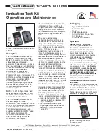
ZERO THE DIGITAL STATIC FIELD
METER
Turn on the meter with the ON/OFF
slide switch. Press the push button
down so that it is in the lower or
MEASURE position. Make a connection
between the Conductive Plate and the
meter case either through your finger or
a test lead. Point the meter toward a
GROUNDED metal surface. If the
display does not read “0.00”, adjust the
ZERO knob until the display reads
“0.00”. Although you must be careful
not to contact the recessed sensor
plate, the amount of spacing between
the instrument and the target is not
critical when zeroing the instrument.
NOTE:
For accurate measurements, the
Field Meter should be grounded. The
meter has a conductive case that
provides a ground reference for the
measuring circuit. Alternatively, the
person holding the meter should be
properly grounded.
MAKING A MEASUREMENT
Locate the Test Kit in an ionised
environment at the appropriate distance
from the device under test. The static
field displayed is the actual balance of
the ioniser or voltage offset. If the
numeral “1” appears on the left side of
the display, the meter’s range of 20 kV
per inch has been exceded. (See
Figure 3)
NOTE:
When testing pulsed ionizer
systems, the voltage displayed is
constantly changing. This pulse rate
may be faster than the display update
rate of the Field Meter, therefore the
displayed voltage is an average of the
actual voltage. The output of the
fieldmeter is useful in this situation for
more accurate measurements.
HOLDING LAST READING
Press the MEASURE/HOLD pushbutton
so that it releases to the upper or HOLD
position. This will freeze the reading
from the object on the display and
allows the operator to move the meter
where it may be more easily read, or
saved for later reference. In the HOLD
position the red LED will illuminate. The
analog output signal is also held.
Unit 17. Millbrook Business Park, Sybron Way • Crowborough, East Sussex TN6 3JZ United Kingdom
Phone: 00 44 (0) 1892-665313, Fax: 00 44 (0) 1892-668838 • E-mail: [email protected], Internet: Charleswater.co.uk
PPE-5084.E
Page 2 of 4
© 2007 CHARLESWATER LTD.
Per ESD TR53-2006 Compliance
Verification of ESD Protective
Equipment and Materials Air Ioniser Test
Procedure Initial Test Setup
“Measurements should be made at the
location where ESD sensitive items are
to be ionised. Air ioniser heaters and
air filters (if so equipped) should be left
in their normal conditions during test.”
TAKING DISCHARGE TIME
MEASUREMENTS
In order to verify that an ioniser is
operating properly it is also important
that its ability to neutralize or discharge
static electricity is measured. The
following procedure will measure an
ioniser's discharge time.
OPERATING THE CHARGING UNIT
The Charger has a momentary rocker-
switch that powers the unit. Holding the
switch forward / backward supplies
power to the output terminals.
Thousands
Hundreds
Tens
Figure 4. Reading the Digital Static
Fieldmeter
Figure 3. Auditing ionisation equipment
with the Digital Static Field Meter and
Conductive Plate
ANALOG OUTPUT
The “RECORD” output jack located on
the face of the meter accepts a
standard 2.5mm monaural phone plug
and is provided so the output of the
Digital Static Field Meter may be
connected to an oscilloscope, strip chart
recorder, external meter or other device.
Use the included cord to achieve a
connection between the field meter and
alternate measuring instrument. ±10
mV at this jack corresponds to ±1 kV.
Output Contact
Rocker Switch
FRONT VIEW
BACK VIEW
Figure 5. Charger features and
components
Touch Plate
Battery
Compartment
OUTPUT CONTACTS
The output contact is connected to an
internal power source. When the touch
plate located underneath the unit is
connected to ground, the output contact
will provide a charge of the indicated
polarity. The charger is designed so
that an operator can press the power
button and touch the touch plate
simultaneously with the fingers of the
same hand.


