
030-300377 Rev. A
Section CFDP-EL-X-801
−
CFDP
t
EL BACKBOARD CABLING INSTALLATION GUIDE
−
2
0707I1P3
VELCRO
is a registered trademark of Velcro Industries B.V.
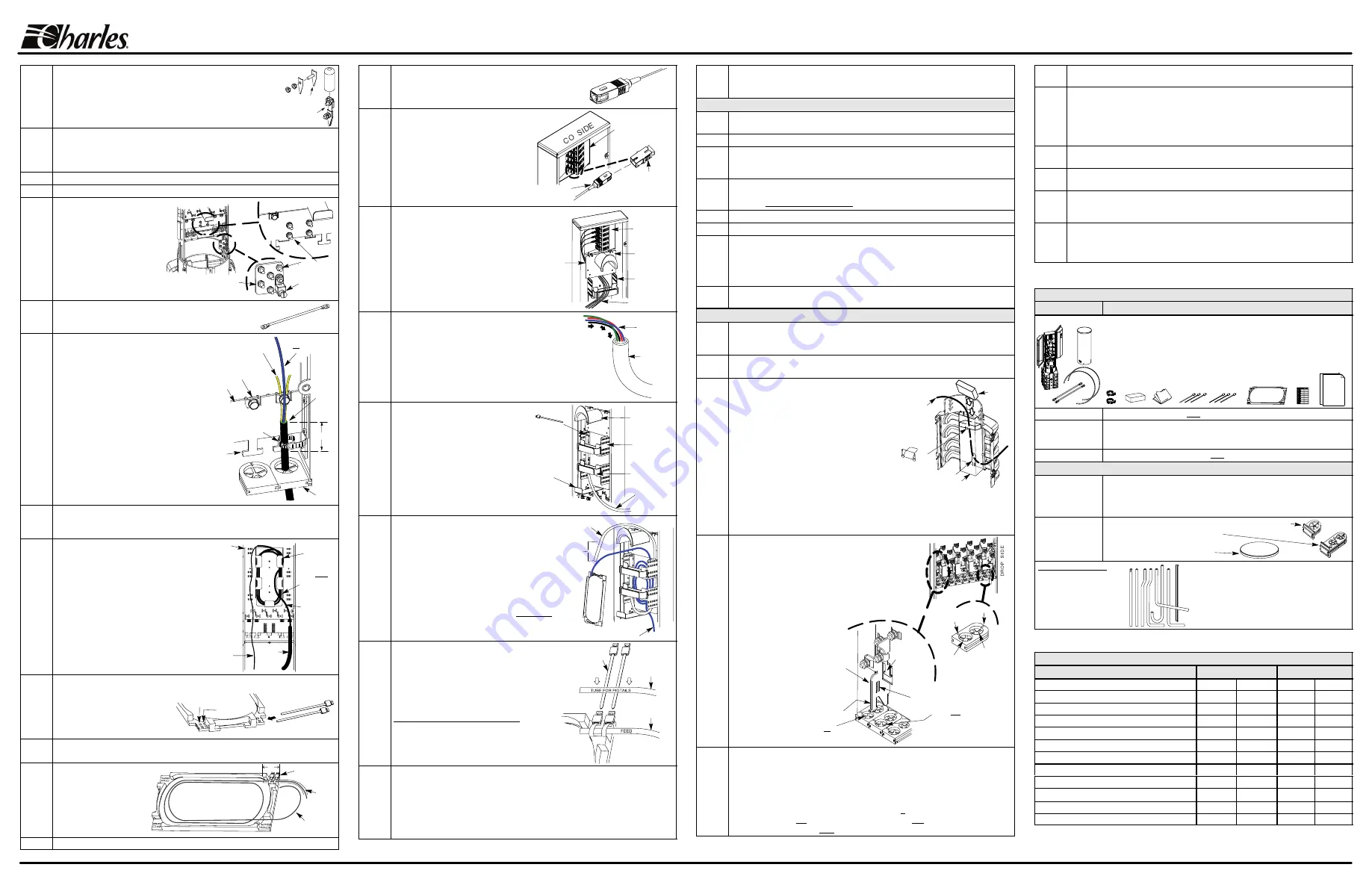
16.
Attach bond clamp to cable.
To prepare the cable for bonding to the
pedestal bonding plate, attach a company-approved cable bond
clamp to the cable/shield at the sheath cut. Always follow clamp
manufacturer instructions or company practice to attach cable
bond clamps, as procedures and clamps used to bond cables
may vary per location, application, and cable type and size.
Sample
cable bond
clamps
17.
Cut to length then remove buffer tube.
Measure then make a mark on the buffer
tube approximately 32" from the cut end. Using local company procedures and
tools, and being careful to avoid the fiber inside the tube, score the tube at the mark
and remove the 32" length of surplus tube and discard it.
18.
Clean fibers.
Per company practice, clean the fibers.
19.
Attach backboard.
If still removed, re-attach the backboard (see Step 9).
20.
Connect earth ground to
ground lug.
Per local codes
and/or company practice, install
an earth ground wire of proper
gauge from the earth ground to
the pedestal at the ground
plate’s ground lug. Always
perform grounding prior to cable
attachment.
Attach earth
ground to lug
Attach bond
straps to posts
Ground plate
Alternate bonding area
21.
Bond cable to ground plate.
Attach a bond strap (provided)
from the cable bond clamp (shown in Step 16) to one of the
bond posts (see Step 20 for bond post locations).
Bond strap
22.
Cable
bond clamp
(optional) not
shown in this view.
Secure cable to backboard’s T tie-down.
First, if the cable has strength members
(and they were not termininated in an
optional cable bond clamp), loosen the
strength member clamp located above the
chosen grommet, and slide the strength
members under it. Next, place the cable
against the cable mounting plate at the T
tie-down, and vertically align the cable so
the sheath cut is midway between the T
and strength member clamp above it
(about 1.5" above the bottom of the T).
Hold the cable in this position and secure
it to the T by opening and firmly affixing
a hose clamp around both the cable
and T tie-down.
Strength member
(under clamp)
Hose clamp
(open and install around
cable and T)
Buffer tube
(not under clamp)
Cable
sheath
cut line
T
tie-down
1.5"
Strength member
clamp on cable
mounting plate
Grommet
Mounting
plate
Bottom
of T
23.
Tighten strength member clamp (optional)
.
If the strength members were placed
under the strength member clamp in Step 22
, secure them by tightening the hex nut
of the strength member clamp. Trim the strength members per company practice.
24.
Route the tube/fiber into fiber basket.
Route the buffer tube up through the
bottom opening of the fiber basket, and
wrap the length of tube inside the basket
(about 2 loops). Secure the tube to the
inside walls of the basket with cable ties,
especially where it first enters the
basket, but do not secure the last 3 feet
of tube. After the tube is attached to the
splice tray in Step 26, this 3’ length will
allow the technician sufficient tube slack
when the splice tray is accessed for fiber
splicing.
Fiber
basket
CO side of
backboard
Begin to route the
buffer tube up
through the bottom of
basket, attach it to
the basket’s inside
wall with a cable tie,
and loop it two times.
See steps 26 & 27 to
attach the tube end
to a splice tray and
wrap fiber in the
splice tray.
Fiber
(approx. 32")
Cable
Buffer tube
(approx. 4.5
feet)
Attach buffer
tube to inside of
basket here
where it first
enters basket.
25.
Prepare a splice tray for tube attachment.
Prepare a splice tray (provided) by
removing the cover and starting
two cable ties at a top tray corner,
using the inner tie-down slots.
Two trays are advised if using
more than 12 pigtails.
Cable ties
Outer cable
tie-down slots
Choose a tray corner
Inner slots
26.
Attach tube to tray.
Overlap the buffer tube onto the tray corner about 1" (see Step
27), then secure the tube to the tray with the two positioned cable ties.
27.
Store fibers in splice tray.
Per
company practice, wrap and
store the fibers in the splice
tray for later slicing, then
attach the tray cover.
Use additional trays
as needed.
Tube,
with
fiber
inside
Secured
cable ties
Fiber
1"
If more than 12 pigtails will be
spliced, additional splice
tray(s) can be used. Always
follow company practice.
28.
Label the tube.
Label both tube ends, per company practice.
29.
Locate or obtain SC-type pigtails.
Separately-ordered SC/APC- and
SC/UPC-type pigtail kits are available from Charles (see
Table 2). Obtain the correct type of pigtails for the
Interconnect pedestal used in this installation.
30.
Attach SC-type connector end of pigtails.
Attach
the connector end of the SC-type pigtails to the
SC-type bulkhead adapters at the top of the
backboard. Remove the caps from the
adapters prior to inserting the connect-
ors. Follow company practice for correct
cable color-coding, and consult the
label on the front side of the bulkhead
to locate the proper line numbers.
(Adapters not removable.
Adapter #1 is inner and
top-most one.)
Preconnectorized bulkhead
at top of backboard
Plug connector into adapter.
Sample of a
bulkhead adapter
900-micron SC-type
connector pigtail
31.
Route pigtail
fibers behind
pigtail
protection
plate.
Route pigtails behind
protection plate.
Once all pigtail
connectors are attached to the
bulkhead, route their free ends
(either singly or collectively)
behind the pigtail protection plate,
starting at the left side of the plate,
then guide them down into the
fiber basket area.
Pigtail
protection
plate
Adapter
bulkhead
Fiber
basket
Free ends of
pigtails
32.
Group
ends of
pigtails
and insert
into tube
Route free ends of pigtails through transportation
tube.
Provided are two 3-foot lengths of plastic 1/4"
tubing to protect the 900-micron pigtail cables. Gather
the free ends of the connected pigtails
(12 pigtails per tray
and tube),
align their ends as a group, and collectively
guide them into a transportation tube. Grouping the
fibers provides greater rigidity. Slide the fibers through
the tube until the free ends exit the opposite tube end.
Transportation
tube
Pigtail
ends
33.
Secure
transportation tube
to basket here (top
inside wall) with
cable tie
Attach one end of transportation
tube to the basket.
With a cable
tie, doubled over, attach one end of
the transportation tube to the top,
left, inside wall of the fiber basket.
Fiber basket
Transportation
tube
Bend-radius
control
Bottom splice tray tab
Pigtails and feed tube not
shown, for visual clarity
Velcro strap
34.
(Optional − trim transportation tube to proper
length.)
Before attaching the tube to the splice
tray, verify the tube length allows the splice tray
(which is attached to the tube in the next step)
to be easily positioned at the front of the fiber basket
after the tube is positioned in the basket. If needed, the
tranportation tube can be cut to length, or trimmed
approximately 4", if company practice is to wrap or
loop it just one time down into the fiber basket and then
up and over the bend-radius control. Alternately, the
uncut tube can be looped twice within the fiber basket,
then routed up and over the bend-radius control.
Trim
tube, if
needed
Feed tube
Transportation
tube
35.
Prepare splice tray, attach other end of transportation
tube.
Again prepare the splice tray for tube attachment,
starting two new cable ties at the same tray corner as
before, using the
outer
tie-down slots. Overlap the
transportation tube onto the tray corner about 1"
(alongside the feed tube),
then secure the tube to the
tray with the two, new, positioned cable ties.
If splicing is not performed at this time, wrap
the pigtails in the tray per company and tray
manufacturer instructions, and continue with
Step 36. If splicing is to be performed at this
time, proceed to Step 38.
Cable
ties
Use same tray
corner and two
NEW ties.
Transportation
tube for pigtails
(12 pigtails per tube
recommended)
Feed buffer tube
Splice tray
36.
Perform tube management.
Always keep tubing neat and free of kinks. To man-
age the tube slack, loop and store the tubes inside the fiber basket, and hang the
tube-end with the attached splice tray up over the bend-radius control near the top
of the backboard. If desired, starting at the splice tray, attach the length of trans-
portation tube to the feed tube with cable ties at short intervals, for easy joint tube
management. Allow the splice tray to rotate freely when looping the tubes for
storage, to avoid stressing and kinking the tubes, which could cause fiber damage.
37.
Close the pedestal (optional).
If splicing or drop cable installation will be perform-
ed at a later time, do Steps 44-45 now to secure the splice tray(s) and to close the
pedestal. Go to Step 38 to perform splicing. Go to Step 46 to install drop cables.
Splicing Fibers at the CFDP Pedestal
38.
Obtain tools.
Prepare the area for splicing, and assemble and prepare any equip-
ment and tools needed to splice fibers. Review all the cautions and warnings herein.
39.
Open pedestal.
Remove the dome and open the CO side door, per Steps 3 and 4.
40.
Remove the splice tray(s) from the backboard.
Loosen the VELCRO
straps that
secure the splice tray(s) and pull out the tray(s), unwinding/rotating it and the tubes
attached to it. Detach the clear plastic cover from the splice tray(s).
41.
Perform splicing.
Unwrap the working fibers to be spliced, perform all fiber splicing
at this time, and when complete, route/place the spliced fibers back into the splice
tray(s), all per local/company practice and product manufacturer’s instructions.
42.
Label and identify splices/tray.
Per company practice, label/identify the splices.
43.
Cover splice tray(s).
Re-attach the cover(s) to the splice tray(s).
44.
Secure tray.
Secure the splice tray(s) to the backboard. To do this, wind or rotate the
tubes and the tray(s) as needed to loop and store the tubing in the fiber basket, then
hang the splice tray(s) from the bend-radius control by routing the last foot of tubing
over the bend-radius control. Secure the tray(s) to the tabs at the front of the fiber
basket with the provided VELCRO
straps. See Step 34 for alternate tube routing.
45.
Re-check foam plug placement and cable management, and close the pedestal.
Perform Steps 54 through 56 to carefully close up the pedestal.
Installing Fiber Drop Cables
46.
Dig trench from premises to pedestal.
Per company practice, prepare a trench to
run the drop cable to the pedestal. Clear the soil from the bottom front of the base,
where the cable enters at the drop cable access hole.
47.
Run the drop cable.
Route the preconnectorized drop cable through the trench to
the pedestal base. Verify 9 feet of cable will be available above the ground line.
48.
cables are routed through the base to their final
length), re-install the plug by placing it in front of the
cables (cables at the back of the channel), angling the plug’s front edge down and
forward toward the first rib of the base front, and sliding it down and forward until it
rests on top of the base’s first rib. Press down on the plug’s back edge until it rests
on the bent flange at the rear of the channel.
Bring cable into base through drop cable
channel or conduit.
Per company practice, route
the drop cable through the drop cable access
hole at the bottom front of the base and push it up
through the channel (or conduit) provided for the
drop cables. At the top of the channel, guide the
cable between the foam plug (installed at the top
of the channel) and the back wall of the channel.
If the plug dislodges during cable routing (after all
(Slide plug into
channel, set on
bent flange &
first rib of base)
Base Interior View,
Front Half
Foam
plug
Channel, installed
Bent
flange
Drop cable
Drop cable hole
49.
Route cable through grommet.
At the drop cable side
of the backboard, at the bottom grommet plate, pull or
slide out one of the double-port grommets. Feed the
preconnectorized cable through the grommet port by
slicing into the grommet port at the notch provided in it,
then pressing or sliding the drop cable into the grommet
port at the sliced notch. Slide the grommet down the
cable until it is at the level of the grommet plate. Rotate
and align the grommet with its
slot, and re-insert the
grommet into the grommet
plate. Always populate or
use the rear-most ports
first, for best hand and
tool access and mobility.
Tie-down slot on bracket
(use with front grommet
port to the right)
Rear
grommet
port
Front
grommet
port
Notch
Notch
Cable
mounting
bracket
Tie-down T on bracket
(use with front grommet
port to the left)
Tie-down T
on rear wall
(use with rear
grommet ports)
50.
Secure cable to backboard
. Secure the cable to its appropriate tie-down T or
tie-down slot (see the drawing in Step 49) with a hose clamp. If cable ties are used,
per company practice, double the tie over the cable and T or slot, crisscross it, and
tighten the tie. Cables that are routed through rear grommet ports should use the
T’s on the backboard rear wall. T’s (and slots) are also provided on the cable
mounting brackets which are perpendicular to the back wall. Use the bracket T’s
and slots with the front grommet ports (the bracket T is used with the front port of
the grommet to the left of the bracket, and the bracket slot is used with the front
port of the grommet to the right of the bracket).
51.
Label drop cable
. Label the/all drop cable(s) with a cable marker or label. This
facilitates later cable identification for future troubleshooting, splicing, or rework.
52.
Route, secure, and connect drop pigtail.
Route and loop the drop cable pigtail
around the inside perimeter of the drop side backboard and hang the last slack loop
from the bend-radius control. Size the loops so that the connector will easily (with-
out tension) reach the appropriate bulkhead adapter. Secure the cable to the back-
board tie-down slots with cable ties at regular intervals. Plug the first connector into
adapter 1 at the top front corner. Adapter 2 is directly below it in the same column.
53.
Prepare all drops.
Repeat Steps 46-52 for all customer drop cables ready for
installation and connection at this time.
If
splicing is to be performed, go to Step 38.
54.
(Re)Place foam plug.
Verify the foam plug is properly installed in the drop channel
(see Step 48). If it was removed or dislodged, re-install it at this time.
55.
Re-check cable management & lock inner door(s).
Verify all tubing is neat and not
kinked, and that no cables, ties, wires or tubes protrude beyond the backboard walls.
Close and lock the inner doors by turning all cup-washer screws clockwise until tight.
56.
Close the pedestal.
Locate the outer dome and orient it so the snap lock faces the
front (the Charles logo is on the base front). Slide the dome down over the back-
board, align the dome’s snap lock with the base’s latch catch, and allow the self-
locking dome to drop down in place. An audible click" indicates the dome is locked.
Table 1. Branch or Stub-End Configuration Installation
Table 2. Model Numbers and Ordering Information
Model #
CFDP
t
Description
CFDP10-EL18
CFDP
Interconnect Pedlock
OSP Pedestal, with a 10" diameter, locking, exterior
dome, a square, 2-piece, expanded-capacity, split base, a weather-tight interior
enclosure with two locking doors, a removable backboard for fiber cable routing,
attachment, storage, and splicing (tray capacity = 5 trays/120 splices at 24 fibers per
tray), a pre-connectorized bulkhead with 18 SC/APC adapters, 4 single-port 1"
diameter feed grommets and 9 double-port 0.625" diameter drop grommets for 18
drops, one FOSC B splice tray, a ground/bond plate and two 3’ lengths of
transportation tubing. Includes all equipment shown herein.
CFDP10-EL18C
Same as above but with SC/UPC-type adapters in the interconnect bulkhead.
CFDP12-EL24
Same as CFDP10-EL18 but with 24 SC/APC adapters in the pre-connectorized
bulkhead, a 12" dome, 6 single-port 1" dia. feed grommets, 12 two-port 0.625"
diameter drop grommets for 24 drops, and an 8 tray capacity.
CFDP12-EL24C
Same as CFDP12-EL24 but with SC/UPC-type adapters in the bulkhead.
Optional Equipment for Use with CFDPs
97-SCAPC18PT
97-SCUPC18PT
97-SCAPC24PT
97-SCUPC24PT
Kit of 18 fiber pigtails: SC/APC-type connector, color-coded, 900 micron, 3 meters
Kit of 18 fiber pigtails: SC/UPC-type connector, color-coded, 900 micron, 3 meters
Kit of 24 fiber pigtails: SC/APC-type connector, color-coded, 900 micron, 3 meters
Kit of 24 fiber pigtails: SC/UPC-type connector, color-coded, 900 micron, 3 meters
97-001911-A
97-001753-A
97-PKOR010A
Grommets, feed-side type, one 1" port per grommet, 50-piece kit.
Grommets, drop side, middle type,
two 0.625" ports per grommet, 50-piece kit
Dome cap, high visibility, orange, 10"
Strong durable solution for protecting wires
that are mounted to buildings and utility poles
PVC construction: lightweight and easy to cut
Various bends, lengths, offsets, and notches
Available in 7/8" and 1.25" diameters
Riser Pipes & U-Guards
119 series (7/8" risers)
122 series (7/8" U-guards)
219 series (1.25" risers)
222 series (1.25" U-guards)
Various replacement parts are available. Contact Charles Industries for more information.
Table 3. Physical Specifications
Feature
10" dome models
12" dome models
Height, overall
50.5 in.
128.3 cm
50.5 in.
128.3 cm
Height, base only, incl. collar (stake only for IPS)
18.5 in.
47 cm
18.5 in.
47 cm
Height, dome only
35.5 in.
90.2 cm
35.5 in.
90.2 cm
Height, base bottom to ground line
8.5 in.
21.6 cm
8.5 in.
21.6 cm
Height, dome top to ground line
42 in.
107 cm
42 in.
107 cm
Depth, base (front to back)
12.8 in.
32.5 cm
15.1 in.
38.4 cm
Width, base (side to side)
13.9 in.
35.3 cm
16.1 in.
41 cm
Diameter, base collar, O.D.
10.75 in.
27.3 cm
12.75 in.
32.4 cm
Diameter, base collar, I.D.
10.3 in.
26.2 cm
12.3 in.
31.2 cm
Diameter, dome, O.D.
(not the cap)
11.25 in.
28.6 cm
13.25 in.
33.6 cm
Diameter, dome, I.D.
10.85 in.
27.6 cm
12.85 in
32.6 cm
Weight
36 lbs.
16.4 Kg
44 lbs.
20 Kg
NOTE: All dimensions and weights are approximate.