


GB
50
CN
Gr
Fr
SP
PT
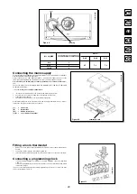
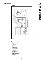
Figure 13
0207_0405
Honeywell gas valve
SIT gas valve
a
a
b
b
Pc
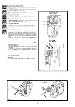
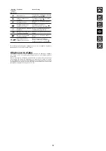
Gas change modalities
A Qualified Service Engineer may adapt this boiler to operate with natural gas (G. 20) or
with liquid gas (G. 30, G. 31).
The procedure for calibrating the pressure regulator may vary according to the type of
gas valve fitted (HONEyWELL or SIT; see figure 12).
Carry out the following operations in the given sequence:
A) substitute the main burner injectors;
B) change the modulator voltage;
C) proceed with a new max. and min. setting of the pressure adjusting device.
A) Substitute the main burner injectors
• carefully pull the main burner off its seat;
• substitute the main burner injectors and make sure you tighten them fast to avoid
leakage. The nozzle diameters are specified in table 2.
B) Change the modulator voltage
• remove the 2 screws securing the control board cover and hinge it upward;
• set the jumper or the switch, according to the type of gas used, as described in the
chapter on page 52.
C) Pressure adjusting device setting
• connect the positive pressure test point of a differential (possibly water-operated)
manometer to the gas valve pressure test point (Pb) (Figure 12); connect, for sealed
chamber models only, the negative pressure test point of the manometer to a “T”
fitting in order to join the boiler adjusting outlet, the gas valve adjusting outlet (Pc)
and the manometer. (The same measurement can be carried out by connecting the
manometer to the pressure test point (Pb) after removing the sealed chamber front
panel);
If you measure the pressure of burners by different means you may obtain an altered
result in that the low pressure created in the sealed chamber by the fan would not
be taken into account.
C1) Adjustment to rated output
• open the gas tap and rotate knob (1) to set the boiler to the Winter setting (
);
• open a hot water tap to reach a minimum 10 l/minute flow rate or ensure that maximum
heating requirements are set;
• remove the modulator cover;
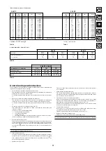
• adjust the tube brass screw (A) Fig. 13 to obtain the pressure settings shown at table
1 on page 51;
• check that boiler feeding dynamic pressure, as measured at the inlet gas valve
pressure test point (Pa) (Figure 12) is correct (30 mbar for G.30, 37 mbar for G.31,
20 mbar for natural gas);
C2) Adjustment to reduced heat output
• detach the modulator feeding cable and unscrew the (B) Fig. 13 screw to reach the
pressure setting corresponding to reduced heat output (see table 1 on page 51);
• connect the cable again;
• fit the modulator cover and seal.
C3) Final checks
• apply the additional dataplate, specifying the type of gas and settings applied.
SIT Gas Valve
mod. SIGMA 845
Figure 12
Honeywell Gas Valve
mod. VK 4105 M
9912221500
0207_0406
Pc
Pb
Pa
Summary of Contents for initia MASTER 2.24 CF
Page 39: ...0609_1503 ...
Page 42: ...INITIA MASTER SPARE PARTS CATALOGUE September 2006 ...
Page 43: ......
Page 45: ......
Page 46: ......


