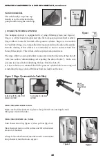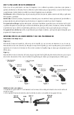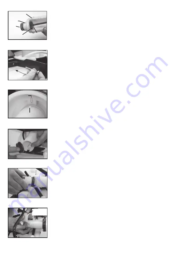
Figure 10
Figure 11
Figure 12
Protective
Dust Cap
9E
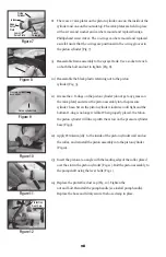
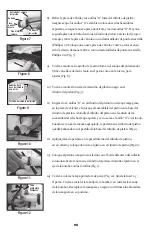
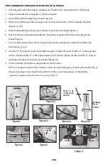
8) There are 2 valve plates on the piston cylinder, one on the inside of the
cylinder and one on the outside top. The valve plates are held in place
with a screw and washer and can be removed and replaced using a
Phillipshead screw driver. The 2 o-rings can be removed and replaced
as well. Insure that the o-rings are positioned in the o-ring grooves in
the piston cylinder (Fig. 7).
9) Reassemble frame assembly to the sprayer tank. Use a socket wrench
on both the bolt and nut to tighten (Fig. 8).
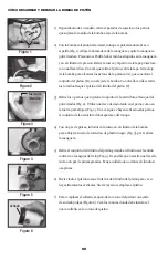
10) Reassemble the black plastic retaining nut to the piston
cylinder (Fig. 3).
11) Grease the 2 O-rings on the piston cylinder (do not get any grease on
the valve plate) and screw the piston assembly into the pressure
cylinder base. Screw the piston cylinder clockwise until tight and the
bottom O-ring is no longer visible. When properly placed, the tab on
the piston cylinder will line up with the arrow on the pressure cylinder
base (Fig.9).
12) Apply Petroleum jelly to the inside of the piston cylinder wall and on
the collar, and reinstall the piston assembly into the piston cylinder
(Fig.10).
13) Insert the piston at an angle with the leading edge of the collar placed
over the slot in the piston cylinder (Fig. 11). Bolt the piston assembly to
the pump shaft using the lever bolts (Fig. 1).
14) Replace the protective dust cap (Fig. 12). Tighten the
nut and bolt. Reinstall the pump handle (see install pump handle).
Replace the hose and firmly secure the hose clamp in place.
Figure 7
Piston
Cylinder
Intake
Upper
Valve
Plate
Lower
Valve Plate
Outlet
Passage
Figure 9
Pressure cylinder
base arrow
Piston cylinder tab
Figure 8


