Chameleon Labs
Model 7602 MKII
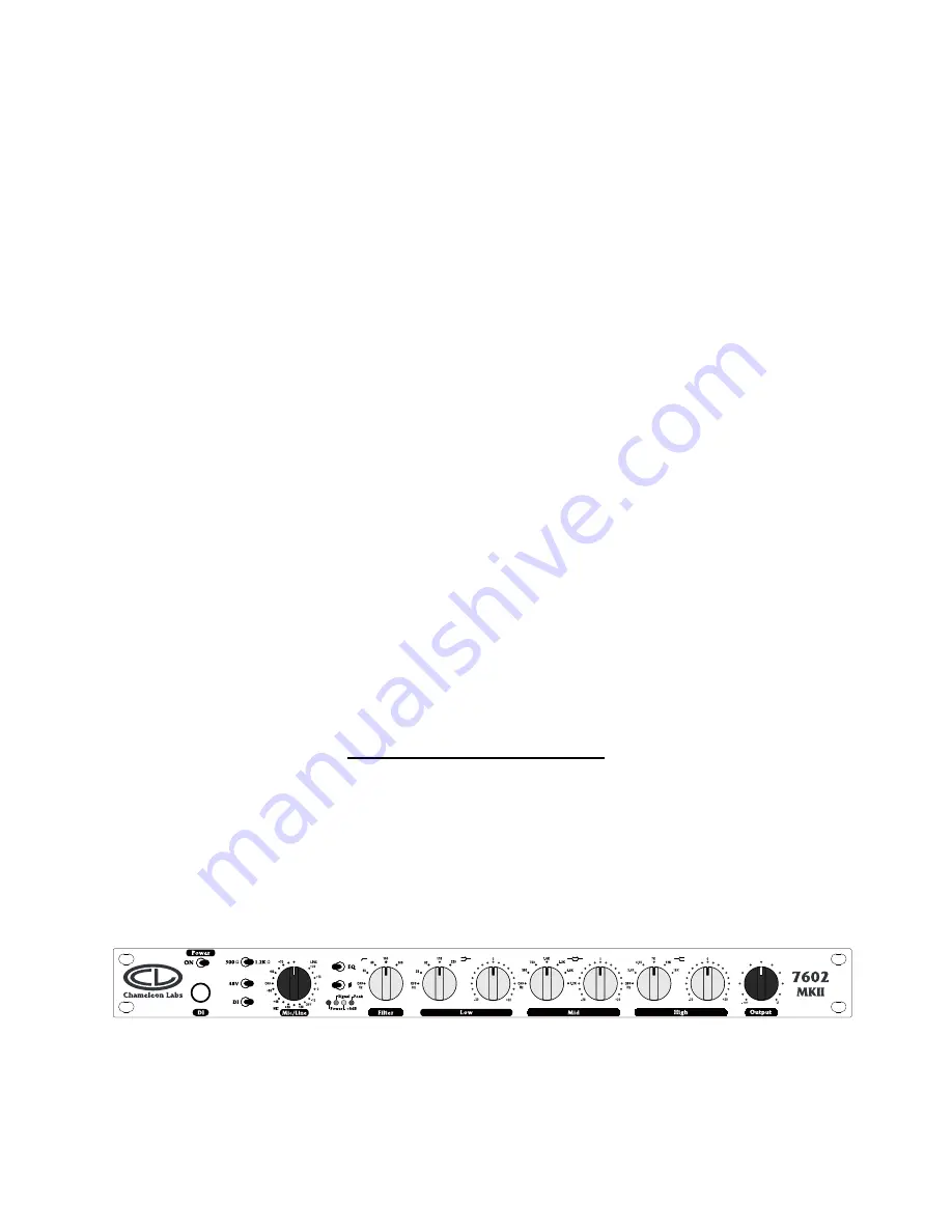
Microphone Preamplifier and Equalizer
Owner’s Manual
704 228
th
Avenue NE, # 826
Sammamish, WA 98074
206-264-7602
www.chameleonlabs.com
Revision A June, 2008
1
Page 1: ...Chameleon Labs Model 7602 MKII Microphone Preamplifier and Equalizer Owner s Manual 704 228th Avenue NE 826 Sammamish WA 98074 206 264 7602 www chameleonlabs com Revision A June 2008 1...
Page 2: ...e class A circuitry This unit is made with 100 discrete components hand wound transformers and was fabricated to precisely match vintage counterparts manufactured in the early to mid 70 s The Chameleo...
Page 3: ...he front panel 48VDC phantom power selector on the front panel 20 position gold contact rotary gain switch for both Mic and Line sections Output level control functions as a fader when going straight...
Page 4: ...ut impedance to either 300 or 1 200 Ohms 48V Switch This switch supplies 48VDC Phantom Power to the Microphone Input XLR jack DI Switch This switch routes the Direct Input jack into the unit Microphon...
Page 5: ...e second LED indicates the presence of signal The third LED indicates the presence of a 4 dB signal The fourth LED indicates the presence of a peak amplitude signal Filter This is a high pass filter w...
Page 6: ...elections 16k 12k 7k 4 9k and 3 4k This section adjusts the selected frequency and all others above it The gain control provides 20dB of boost or cut Output Acting as a console fader this control is p...
Page 7: ...ction is made using the balanced TRS jack on the front panel The connector is wired with the TIP being positive The RING being negative and the SLEEVE being ground shield Line input connections are ma...
Page 8: ...The CPS 1 power supply contains a toroidal transformer to reduce 60Hz hum To insure quiet operation mount the power supply at least one rack space away from the Model 7602 MKII main unit and locate th...
Page 9: ...ug is misaligned and should be rotated for a correct fit DO NOT FORCE the power connector The power pin is wired as follows Pin 4 is Audio Ground shield Pin 3 is 48 Volts D C Pin 2 is 24 Volts D C Pin...
Page 10: ...matches most professional microphones used today if you have microphones that require a lower impedance you may toggle the switch to 300 You can toggle between the selections without damage to the mic...
Page 11: ...the rear panel 6 When an electronic instrument such as an electric guitar is used it may be plugged directly into the DI plug located on the front panel Toggle the DI switch to select this input devi...
Page 12: ...9 When the optional CPS 1 is used the POWER switch is inoperative and the power is controlled by the switch on the CPS 1 12...
Page 13: ...ontact the manufacturer Service is provided for products beyond the warranty period Seller warrants that the goods are described in this agreement but no other express warranty is made in respect to t...
Page 14: ...cations Input impedance Microphone 300 or 1 200 ohms Line 10 000 ohms D I 100 000 ohms Sensitivity Microphone 80dBm to 20 dBm in 5dB steps for 0 dBm output Line 20 dBm to 10 dBm in 5 dB steps for 0 dB...
Page 15: ...Maximum output 26 dBm into 600 ohms or 20dBm into 150 ohms Output impedance 600 ohms balanced source impedance 75 ohms Frequency Response 11 Hz 77 65 kHz 3 dB Level variation is less than 0 2 Distort...