background image

CHA 40/20 FD 

Page 7 


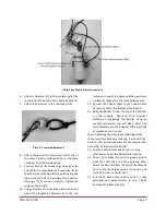
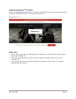
Plate 3. Fan Dipole Center Connections.


6.


Attach a Carabiner (h) to the Insulator (g) at the 
center end of the other 7 MHz Antenna Wire (e). 

7.


Attach the Carabiner to the Top Eyebolt (b). 


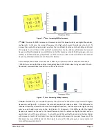
Plate 4.  Paracord Attachment. 

 
8.


Attach the Insulator at the center end of one of 
the  other  14  MHz  Antenna  Wire  to  the  same 
Carabiner from the previous step.   

9.


Connect  both  of  the  Spade  Lugs  from  steps  (8) 
and (9) to the same Antenna  Connection (c) on 
the other side of the BALUN (a) by placing a spade 
lug around the bolt on each side of the washer, 

forming a “V”, as show

n in plate (3).  Tighten the 

wing nut finger tight.   

10.


Using a Bowline or similar knot, attach the end of 
one  of  the  lengths  of  Paracord  (i)  to  the  end 

Insulator on one of the Antenna Wires, as shown 
in plate (4).  Repeat for the other Antenna wire. 

11.


Connect  the  Coaxial  Cable  to  the  Coaxial  Cable 
Connection (d) on the bottom of the BALUN.   

12.


Raise the BALUN to near the top of the Mast (k) 
or  other  support.    Figure  (2)  show  a  typical 
method  of  suspending  the  BALUN  using  an 
eyebolt,  suspension  line,  and  cleat.   

Mast  and 

mast hardware are not included.  Other methods 
of suspension can be used. 

When tightening the wires in the followings steps, 
the wires should have very little sag - but should not 
be taut.  Also, be sure the wires are not tangled with 
each other at the top of the BALUN. 
13.


Pull the 7 MHz Antenna Wire until it is fully 
extended and near the desired end location.   

14.


Drive  a  Tent  Stake  (m)  into  the  ground  around 
three  feet  past  the  end  of  the  Antenna  Wire.  
Attach the Paracord from the end of the Antenna 
Wire  to  the  Tent  Stake  using  a  round  turn  and 
two half-hitches or similar knot. 

15.


Pull  the  14  MHz  Antenna  Wire  until  it  is  fully 
extended  and  perpendicular  to  the  7  MHz 
Antenna Wire from step (13). 

Summary of Contents for CHA 20 FD

Page 1: ...40 20 Meter Fan Dipole Antenna CHA 40 20 FD Operator s Manual Nevada USA WWW CHAMELEONANTENNA COM VERSATILE DEPENDABLE STEALTH BUILT TO LAST...

Page 2: ...trust insulation to protect you Stay away from all power lines WARNING Never operate this antenna where people could be subjected to high levels of RF exposure especially above 10 watts or above 14 MH...

Page 3: ...nna Without an antenna tuner the Fan Dipole can operate on the 40 and 20m amateur radio bands A wide range antenna tuner will also enable operation on the 17 15 12 and 10m bands Figure 1 Fan Dipole An...

Page 4: ...are the primary method of HF radio wave propagation HF radio waves on a frequency below the critical frequency found by an ionosonde are reflected off one of the layers of the ionosphere and back to...

Page 5: ...r is used to match the antenna and coaxial cable preventing feedline radiation The BALUN is also used as the mechanical and electrical center attachment points for the antenna b Top Eyebolt The Top Ey...

Page 6: ...uded to wrap around the Line Winders for use in field tuning the antenna Antenna Installation The Chameleon AntennaTM 40 20 Meter Fan Dipole antenna can be deployed as a Flat Top horizontal dipole or...

Page 7: ...other Antenna wire 11 Connect the Coaxial Cable to the Coaxial Cable Connection d on the bottom of the BALUN 12 Raise the BALUN to near the top of the Mast k or other support Figure 2 show a typical...

Page 8: ...and installed in variety of ways in the field all of which affect the resonant frequency of the antenna Use this simple field tuning procedure to quickly and easily adjust the resonant frequency for e...

Page 9: ...you can say that the antenna is resonating close to 150 KHz too low Using our rule of thumb from above you would take three half turns off the Line Winder Figure 4 2nd Case Decreasing SWR by frequency...

Page 10: ...000 KHz we should add just one half turn on the Line Winders to increase the resonant frequency of the dipole to around 7 150 KHz Some trial and error may be necessary but remember as long as the SWR...

Page 11: ...on some frequencies indicate a tuning issue perform the Field Tuning procedure 3 Check the Antenna Wire Spade Lug connections on the sides of the BALUN to make sure they are tightly connected and free...

Page 12: ...figures 6 and 7 Power Handling 150 Watts Space Required An area 54 feet in length and 40 feet in width and have or be able to accommodate a 20 foot mast or other vertical support near the center of th...

Page 13: ...f 12 months from the date of purchase To obtain warranty service return all components of the system to Chameleon Antenna at your expense Chameleon Antenna will repair or replace defective components...

Page 14: ...Portable Antenna Pioneer References 1 Silver H Ward editor 2013 2014 ARRL Handbook for Radio Communications 91st Edition American Radio Relay League Newington CT 2 1987 Tactical Single Channel Radio C...

Reviews: