background image

7

UP

CE

ILI

NG

 M

OU

NT

 O

NL

Y

9

10

11

NOTICE

5

6

8

1

4

12

13

3

2

37

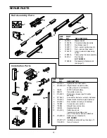
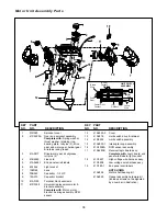
REPAIR PARTS

1

3

3

6

7

4

5

5

8

2

Installation Parts

Rail Assembly Parts

KEY

PART

NO. NO.

DESCRIPTION

1

4A1008

Master link kit

2

41A3489

Complete trolley assembly

3

183B112

Rail braces (each)

4

183B111

Rail – center sections (each)

5

183B113

Rail – end sections (each)

6

41A3473

Chain & cable in dispensing
carton

7

41B2616

Cable pulley bracket assembly

8

83A11-2

Rail Grease
NOT SHOWN

41A2848

Rail assembly hardware kit
(see page 7).

KEY

PART

NO.

NO.

DESCRIPTION

1

41A4166

Lighted door control button

2

41A5056-17

Single-function remote control,
housing only (no circuit board)

3

10A20

3V2032 Lithium battery

4

29B137

Transmitter visor clip

5

41A2828

Emergency release rope & handle
assembly

6

217A238

2-conductor bell wire – white & white/red

7

41A4353

Header bracket w/clevis pin & fastener

8

41A5047

Door bracket w/clevis pin & fastener

9

178B35

Curved door arm section

10

178B34

Straight door arm section

11

12B350

Hanging brackets

12

41A5034

Safety sensor kit
(receiving and sending eyes)
with 3' 2-conductor bell wire attached

13

41A5266-1

Safety sensor brackets (2)
NOT SHOWN

41A3475-17

Installation hardware bag (see page 7).

114A2699

Owner's manual

Summary of Contents for Security+ 7420

Page 1: ...aterials carefully Fasten the manual near the garage door after installation The door WILL NOT CLOSE unless The Protector System is connected and properly aligned Periodic checks of the opener are req...

Page 2: ...lly 32 Care of your garage door opener 33 Having a problem 34 Programming 35 36 To add a hand held remote control 35 To erase all codes 35 Multi function remotes 35 To add or change a Keyless Entry PI...

Page 3: ...ring your garage door Before you begin Disable locks Remove any ropes connected to garage door Complete the following test to make sure your garage door is balanced and is not sticking or binding 1 Li...

Page 4: ...in your garage If so a support bracket and additional fastening hardware may be required Installation Step 10 Depending upon garage construction extension brackets or wood blocks may be needed to inst...

Page 5: ...Reversing Sensor Gap between floor and bottom of door must not exceed 1 4 Wall mounted Door Control Motor Unit ONE PIECE DOOR WITHOUT TRACK CLOSED POSITION Cable Pulley Bracket Header Bracket Trolley...

Page 6: ...ing Eye and 1 Receiving Eye with 2 Conductor White White Black Bell Wire attached Safety Sensor Bracket 2 SECURITY Single Function Remote Control Transmitter 2 Motor Unit with 2 Light Lenses Your gara...

Page 7: ...Nut 5 16 18 5 Washered Bolt 5 16 18 x 1 2 2 mounted in motor unit Carriage Bolts 1 4 20 x 1 2 12 Hex Bolt 5 16 18 x 7 8 3 Master Link 2 Ring Fastener 3 Threaded Trolley Shaft 1 Lock Washer 5 16 4 Lag...

Page 8: ...or reversals 3 Assemble lock nuts ensure alignment and tighten NOTE If rail is not assembled exactly as shown trolley will not travel smoothly along length of rail or it will hit against nuts 4 Positi...

Page 9: ...th a 5 16 lock washer and nut NOTE This bolt prevents trolley over travel Keep a 2 minimum between the trolley and this bolt when adjusting travel limits see page 28 Washered Bolt 5 16 18x1 2 Rail Bac...

Page 10: ...nnect the chain to the flat end of the shaft Figure 1 Check to make sure the chain is not twisted 5 Remove the screwdriver ATTACHING THE SPROCKET COVER Insert the back tab in the slot on the back of t...

Page 11: ...opener only on properly balanced and lubricated garage door An improperly balanced door may not reverse when required and could result in SEVERE INJURY or DEATH 3 All repairs to cables spring assembli...

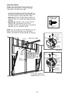
Page 12: ...shown Draw an intersecting horizontal line on the header wall 2 above the high point This height will provide travel clearance for the top edge of the door Proceed to Step 2 page 14 One piece door wi...

Page 13: ...shown Measure the distance from the top of the door to the floor Subtract the actual height of the door Add 8 to the remainder See Example 3 Close the door and draw an intersecting horizontal line on...

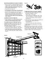
Page 14: ...Garage Door Travel Vertical Centerline Header Wall Garage Door UP CEILING MOUNT ONLY Wall Mounting Holes Optional Wall Mounting Holes The nail hole is for positioning only You must use lag screws to m...

Page 15: ...3 Attach the Rail to the Header Bracket Position the opener on the garage floor below the header bracket Use packing material as a protective base NOTE If the door spring is in the way you ll need hel...

Page 16: ...for setting an ideal door to rail distance Raise the opener onto a stepladder You will need help at this point if the ladder is not tall enough Open the door all the way and place a 2x4 laid flat on t...

Page 17: ...the rail is centered over the door or in line with the header bracket if the bracket is not centered above the door 7 Remove the 2x4 Operate the door manually If the door hits the rail raise the head...

Page 18: ...lling into drywall drill 5 32 holes and use the anchors provided 3 Run bell wire up wall and across ceiling to motor unit Use insulated staples to secure wire in several places Do not pierce wire with...

Page 19: ...wn Secure with an overhand knot at least 1 from the end of the rope to prevent slipping Thread the other end of the rope through the hole in the release arm of the outer trolley Adjust rope length so...

Page 20: ...he black line wire to the screw on the brass terminal the white neutral wire to the screw on the silver terminal and the ground wire to the green ground screw The opener must be grounded Reinstall the...

Page 21: ...her can be installed on the left or right of the door as long as the sun never shines directly into the receiving eye lens The mounting brackets are designed to clip onto the track of sectional garage...

Page 22: ...dge of the track as shown in Figure 1 If your door track will not support the bracket securely wall installation is recommended Wall installation Place the bracket against the wall with curved arms fa...

Page 23: ...WIRING THE SAFETY SENSORS Slide a 1 4 20x1 2 carriage bolt head into the slot on each sensor Use wing nuts to fasten sensors to brackets with lenses pointing toward each other across the door Be sure...

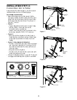
Page 24: ...or panel support and the door bracket Drill 3 16 fastening holes Secure the door bracket using the two 1 4 14x5 8 self threading screws Figure 2A Alternately use two 5 16 bolts lock washers and nuts n...

Page 25: ...INUM STEEL DOORS WITH GLASS PANEL ETC NOT PROVIDED ONE PIECE DOORS Please read and comply with the warnings and reinforcement instructions on the previous page They apply to one piece doors also Cente...

Page 26: ...far apart as possible to increase door arm rigidity Figure 3 Hole alignment alternative If holes in curved arm are above holes in straight arm disconnect straight arm Cut about 6 from the solid end Re...

Page 27: ...s 5 16 Ring Fastener Straight Arm Bolts 5 16 18x7 8 Door Bracket Clevis Pin 5 16 x1 1 4 Curved Door Arm Press the Door Control push button The trolley will travel to the fully closed position Manually...

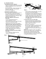
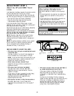
Page 28: ...Adjustment Step 2 If the door does not close completely Increase down travel Turn the down limit adjustment screw counterclockwise One turn equals 2 of travel If door still won t close completely and...

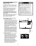
Page 29: ...e control clockwise Make small adjustments until the door completes a close cycle After each adjustment run the opener through a complete travel cycle Do not increase the force beyond the minimum amou...

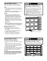
Page 30: ...on the one inch board remove the obstruction and run the opener through 3 or 4 complete travel cycles to test adjustment IMPORTANT SAFETY CHECK Repeat Adjustment Steps 1 2 and 3 after Each adjustment...

Page 31: ...fter 4 1 2 minutes Bulb size is 100 watts maximum Security light feature Lights will also turn on when someone walks through the open garage door With a Multi Function Door Control this feature may be...

Page 32: ...ing garage door If possible use emergency release handle to disengage trolley ONLY when garage door is CLOSED Weak or broken springs or unbalanced door could result in an open door falling rapidly and...

Page 33: ...n of the remote control in your car Check to be sure the antenna on the side or back panel of motor unit extends fully downward Some installations may have shorter range due to a metal door foil backe...

Page 34: ...ravel limits The need for occasional adjustment of the force and limit settings is normal Weather conditions in particular can affect door travel 11 The door reverses for no apparent reason and opener...

Page 35: ...Multi Function Door Control all three buttons are held 4 Release buttons when the motor unit lights blink It has learned the code If light bulbs are not installed two clicks will be heard KG 1 3 9 7...

Page 36: ...our buttons for the present PIN then press and hold the button The opener light will blink twice Release the button 2 Press the new 4 digit PIN you have chosen then press Enter The motor unit lights w...

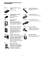
Page 37: ...NO DESCRIPTION 1 41A4166 Lighted door control button 2 41A5056 17 Single function remote control housing only no circuit board 3 10A20 3V2032 Lithium battery 4 29B137 Transmitter visor clip 5 41A2828...

Page 38: ...7 108D68 Lens 8 30B363 Capacitor 1 2 HP 9 12A373 Capacitor bracket 10 41A3150 Terminal block w screws 11 41D3058 Universal replacement motor bracket assembly Complete with Motor worm bracket bearing a...

Page 39: ...n Detecting Control Panel Multi function door control with motion sensor that automatically turns opener lights on for 5 minutes when it detects a person entering the garage Sensor can be easily deact...

Page 40: ...y repair You will be advised of shipping instructions when you call the toll free service number Please include a brief description of the problem and a dated proof of purchase receipt with any produc...

Reviews: