background image

1

2

3

4

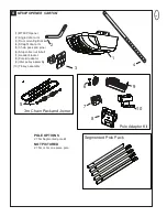
Segmented Pole Pack

3m Chain Pack and Joiner

Pole Adaptor Kit

6

5

7

10

9

8

MT60P OPENER CARTON

(1) MT60P Opener
(2) Angled door arm
(3) Door mounting Bracket
(4) Straight door arm
(5) Chain pack and joiner
(6) Stop collar, nut & bolt
(7) Header bracket
(8) Pole kit adaptor
(9) Idler pulley assembly

(10) Trolley assembly

POLE OPTIONS

2.75m Segmented pole kit

NOT PICTURED

2.75m or 3m one piece pole

4

3

Summary of Contents for Merlin MT60P

Page 1: ...for future reference www chamberlainanz com This manual contains IMPORTANT SAFETY information DO NOT PROCEED WITH THE INSTALLATION BEFORE READING THOROUGHLY MT60P Sectional and Tilt Garage Door Opene...

Page 2: ...or removing covers KEEP THESE INSTRUCTIONS WARNING Failure to comply with the following instructions may result in serious personal injury or property damage Read and follow all instructions carefull...

Page 3: ...s 6 12 Nuts 6 13 4mm Anchors 2 14 R Clip 4 15 8mm Anchors 4 16 Sheet Metal Screw 4 4 9 8 5 6 7 13 12 11 15 10 NOTICE 16 14 2 3 2 A One Piece Door with Horizontal Track Only B Sectional Door with curve...

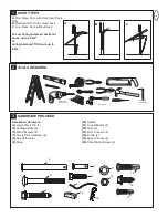
Page 4: ...R CARTON 1 MT60P Opener 2 Angled door arm 3 Door mounting Bracket 4 Straight door arm 5 Chain pack and joiner 6 Stop collar nut bolt 7 Header bracket 8 Pole kit adaptor 9 Idler pulley assembly 10 Trol...

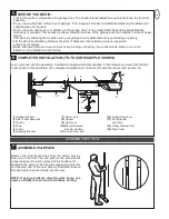
Page 5: ...make sure your garage door is balanced and is not sticking or binding Lift the door about halfway Release the door If balanced it should stay in place supported entirely by its springs Raise and lowe...

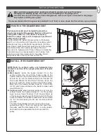
Page 6: ...e pole through the adaptor bracket 3 to the opener then fasten the stop collar above the edge of the lens cover as illustrated Move the stop collar to the open limit on the pole set the stop collar ba...

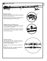
Page 7: ...nd the idler pulley 1 and drive sprocket as illustrated in fig 1 ensuring the chain passes through the trolley assembly 3 NOTE Locate the chain connector as illustrated above approximately 300mm from...

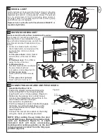
Page 8: ...r more above the floor where space permits INSTALLATION SECTION INSTALL THE HEADER BRACKET UP CEILING MOUNT ONLY UP CE ILI NG MO UN T ON L Y 2 1 50mm or 200mm 3 5 5 B UP 150mm UP CEILING MOUNT ONLY 5...

Page 9: ...r pull down on the trolley arm to disengage the opener Leave the trolley in this position until opener is fastened in place ONE PIECE TILT DOOR You will need a 100mm 4 piece of timber or similar space...

Page 10: ...or manually If door hits the pole raise header bracket 16 A C 3 1 2 2 5 1 2 3 1 B 2 4 1 3 3 2 5 2 3 ATTACH EMERGENCY RELEASE ROPE HANDLE Thread one end of rope 1 through hole in top of red handle so N...

Page 11: ...minutes it will turn off To close gently push diffuser up until engaged Replace burnt out bulbs with Chamberlain 041A0079 or reputable light bulbs 18 3 4 B 1 5 C A 1 2 3 3 1 2 4 A 0 100mm B 150 250mm...

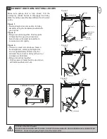
Page 12: ...the hardware provided with your opener Figure 2 Bring arm section together Find two pairs of holes that line up and join sections Select holes as far apart as possible to increase door arm rigidity F...

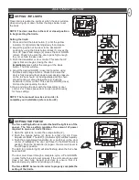
Page 13: ...the door will stop when moving up or down Follow the steps below to set the limits NOTE The door must be in the mid or closed position to begin setting the limits Setting the limits 1 Press and hold t...

Page 14: ...oors doors over 2 5m and when the closing force as measured on the bottom of the door is over 400N 40kg After opener has been installed and adjusted The Protector System accessory can be installed Ins...

Page 15: ...indiciate it is receiving signal from the transmitter 2 Press and release the LRN button 3 The sourtesy LEDs will flash once Ensure the door is clear of obstruction then test the transmitter Using th...

Page 16: ...e LIGHT button on the Motion Detecting Control Panel 6 Continue holding the ENTER and LIGHT buttons while you press the push bar on the Motion Detection Control Panel all three buttons are held 7 Rele...

Page 17: ...across the ceiling to the garage door operator Use insulated staples 5 to secure wire The receiver quick connect terminals are located behind the light lens of the operator Connect the bell wire to t...

Page 18: ...twice resetting the timer to 2 1 2 minutes Repeat again for 3 1 2 minute interval etc up to a maximum of four flashes and 4 1 2 minutes Lock feature Designed to prevent operation of the door from hand...

Page 19: ...7 Model C840 Keyless Entry System 8 Model C77 The Protector SystemTM IR Beams 9 Model CM1702 Quick Release Lock 10 Model 760E Outside Keyswitch 11 Model C379 Wireless Fingerprint Access System 12 Mod...

Page 20: ...1 17 8 B 0 0 8 6 B 0 12 B 0 9 0 6 17 8 B 0 0 3 4 B P D R3 0 0 0 5 2 7 5 m S egmented P ole P ack 0 12 B 0 9 0 5 0 0 1A 6 8 2 9 0 0 1A 7 3 5 0 0 0 1A 6 7 9 3 19 18 4 A 0 2 4 2 0 12 A 0 9 2 8 14 2 A 0...

Page 21: ...itter The portable transmitter may be secured to a car sun visor with the clip provided Additional remotes can be purchased at any time for use in all vehicles using garage Refer to Accessories Any ne...

Page 22: ...otector System if you have installed this accessory If the light is flashing correct alignment If opener light does not flash and it is a new installation repeat Setting the Limit and Force steps 22 a...

Page 23: ...osing It is STRONGLY RECOMMENDED for homeowners with young children Allow a 15 minute cooling period after 5 continuous operations of the opener The opener light will turn on 1 when opener is initiall...

Page 24: ...rom defects in material and or workmanship for a period of 2 YEARS from the date of first purchase from the Seller Please retain your proof of purchase in the unlikely event you require warranty servi...

Reviews: