Chamberlain LMSC1000 Installation Manual Download Page 6

6

Troubleshooting

Problem

Troubleshooting

Resolution

Reader does not read 
tags (Reader LED is 
Red and does not 
change)

Power

Check the power supply voltage at the closest termination to the reader 
(typically at the Wiegand interface module) with a Digital Multi-Meter 
(DMM). You should read >12V DC.

If the wiring distance and gauge are correct and the supply is <12V DC, 
replace the power supply with another rated at 12V DC 3A.

Measure the wiring distance between the reader (mounted) and where 
the power supply plugs in to the main power source. This distance 
should not exceed 50'.

Check the wiring gauge to make sure it is within specifi cation for this 
product (Cat5/6 should never be used for power).

If the above all checks out and the reader recovers with a power 
cycle to both reader and Wiegand module then investigate the main 
(115VAC) supply. If the main power source experiences a brown out 
condition (voltage drops below 100VAC but does not go away entirely), 
this may lock up the reader and cause it to malfunction.

Switch to a separate main power (115VAC) source or install a UPS 
system to provide a more stable power source.

Programming

Remove the serial connector (green, white and yellow wires from 
reader) from the Wiegand interface module and cycle power to both 
devices. If the reader regains normal function then the issue may be in 
the Wiegand interface module.

The Wiegand interface has a arming loop feature that will place the RFID 
reader into standby mode when the loop input is not active. Check the 
arming loop setting of the Wiegand interface module on dip switch S1-5 
and make sure this switch is in the off position. If the setting is off and 
the problem persists, replace the Wiegand interface module.

Final

If the reader does not recover after a power cycle and the above 
troubleshooting does not reveal the problem, there may be an issue 
internally in the reader.

Contact your channel partner and request an RMA to send in the reader 
for repair or order a replacement.

Reader reads RFID 
tags however not at an 
adequate range. (The 
average read range 
should be 20-25')

Power

Check the power supply voltage at the closest termination to the reader 
(typically at the Wiegand interface module) with a DMM. You should 
read >12V DC.

There is a direct correlation between the quality of the power supplied 
to the reader and the reader range. Make sure that the wiring distance 
is kept to minimum (no coiled wire), gauge is correct and the supply 
is   >12V DC. If all checks out proceed to the next section under 
programming.

Measure the wiring distance between the reader (mounted) and where 
the power supply plugs in to the main power source. This distance 
should not exceed 50'.

Check the wiring gauge to make sure it is within specifi cation for this 
product (Cat5/6 should never be used for power).

RFID Tags

You will not experience normal operating range if you are testing 
windshield/headlamp mount tags by hand. The tags need the intended 
mounting surface to achieve normal operating range.

Temporarily mount the tag to intended surface using tape and retest.

Inspect the mounting of the RFID tags and make sure they are mounted 
correctly and away from any interference sources.

Consult the RFID tag installation manual and make sure that the tags are 
mounted correctly.

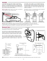
Outside Interference

RFID readers are susceptible to interference from other electronic 
devices and environmental conditions.

Make sure the reader has free line of sight to the RFID tag on the 
vehicle in the road way. It cannot be obstructed in any way by foliage 
(plants, bushes, and trees) or metal (posts, signs, gate arms).

Remove any obstructions that are in front of the reader’s read zone.

Check the area around the installation for other electronic devices that 
may emit noise and interference such as high voltage power lines, 
fl orescent lights, cell phone towers, high power UHF radio transmitters 
or antennas (Including other RFID systems).

Investigate if any of these sources can be temporarily disabled to allow 
RFID reader testing. If the RFID reader range increases when the device 
is disabled then you have located the source of interference. You may 
need to relocate the interference source or RFID reader.

Programming

This reader offers a range adjustment on the Wiegand interface module. 
This default sets the reader range at maximum however this may have 
changed.

Confi rm the read range setting using the steps in the installation manual.

Programming Your LiftMaster tags into myQ

®

 Business

When adding a new credential in myQ

® 

Business™, go to the credentials tab, click “Add new credentials” and when selecting type, choose 

RFID_Tags_LiftMaster.

Summary of Contents for LMSC1000

Page 1: ... weather proof enclosure UL Listed NITW or CYIV Types 3X 3RX 3SX 4X OR 6P U Bolts 2 Reader Specifications Part Number LMSC1000 FCC ID XVY IDRO900MA Dimensions 10 25 x 10 25 x 1 5 Polarization Circular Polarized Frequency range 902Mhz 928 MHz Supported Protocol ISO 18000 6C EPC C1 G2 ISO 18000 6B Read Range 20 30 Feet Depending on Tag Anti Collision Up to 100 tags second Environment Operating Temp 2...

Page 2: ...ions Reader Reader Tag Read Zone Tag Read Zone Correct Driver Side Reader Placement Correct Overhead Reader Placement Correct Passenger Side Reader Placement Reader Mounting NOTE Examples shown are general recommendations final location should be decided upon field testing Step 1 Install mounting bracket to the desired mounting location Attach the round side of the bracket with appropriate screws St...

Page 3: ...WG wire Maximum cable distance between the relay control of the S2W and an external visual audible device is 98 5 ft For applications where multiple RFID readers will be in close proximity this feature can be used to turn on the reader field ONLY when the loop senses the presence of a vehicle When switch 5 is turned on the Wiegand board sends a command to the antenna to turn off the reader field unt...

Page 4: ...GAND OUTPUT REQUEST TO EXIT STATUS STATUS Access Control System PRIMARY RELAY ON WIEGAND INPUT ON OFF 12 V 12 VDC GND 12 V 12 VDC GND SER IN SER OUT GND DATA 1 DATA 0 GND GND LP_INL LP_INH NO CONN A B Normally Open Gate Operator Common WIEGAND INPUT WIEGAND INPUT Black w Dash Wiegand Interface Module LEDs Green PWR Power Solid when power present Green LP Arming Loop Solid when active Blue SET ERR ...

Page 5: ... 2 3 4 5 6 ON OFF ON OFF Beeper Enable Disable By default the LMSC1000 will beep when it reads an RFID tag To toggle this feature turn on or off perform the following steps 1 Place the module in programming mode by setting switch 6 Setup to On left 2 Turn the adjustment pot counter clockwise to the minimum setting 3 Press the Reset button just above the range adjustment to toggle the setting 4 Ret...

Page 6: ... a DMM You should read 12V DC There is a direct correlation between the quality of the power supplied to the reader and the reader range Make sure that the wiring distance is kept to minimum no coiled wire gauge is correct and the supply is 12V DC If all checks out proceed to the next section under programming Measure the wiring distance between the reader mounted and where the power supply plugs ...

Page 7: ...flashes red and top orange LED flashes there may be a wiring issue between the WIM and your access controller Make sure your wiring run is less than the maximum distance of 98 5 ft 107 m With a DMM measure for DC voltage between the Data 1 and COM as well as Data 0 and COM You should read a normal operating voltage of at least 4 9 5V DC A reading of less than this voltage indicates a voltage drop po...

Page 8: ... uses and can radiate radio frequency energy and if not installed and used in accordance with the instructions may cause harmful interference to radio communications However there is no guarantee that interference will not occur in a particular installation If this equipment does cause harmful interference to radio or television reception which can be determined by turning the equipment off and on...

Page 9: ...ries homologuée UL NITW ou CYIV de types 3X 3RX 3SX 4X ou 6P Boulons en U 2 Caractéristiques du lecteur Numéro de pièce LMSC1000 ID de la FCC XVY IDRO900MA Dimensions 10 25 26 cm x 26 cm x 3 8 cm 10 25 po x 10 25 po x 1 5 po 26 cm x 26 cm x 3 8 cm 10 25 po x 10 25 po x 1 5 po Polarisation Polarisée circulaire Plage de fréquences 902 MHz 928 MHz Protocole pris en charge ISO 18000 6C EPC C1 G2 ISO 1...

Page 10: ...uette Zone de lecture d étiquette Emplacements de préférence des étiquettes Emplacements de préférence des étiquettes Emplacements de préférence des étiquettes Lecteur Lecteur Placement correct du lecteur du côté conducteur Placement correct du lecteur au dessus du toit du véhicule Placement correct du lecteur du côté passager Montage du lecteur REMARQUE Les exemples illustrés sont des recommandat...

Page 11: ...maximale entre du câble entre la commande du relais du S2W et un dispositif externe visuel sonore est de 30 m 98 5 pi Dans les applications où de multiples lecteurs RFID se trouveront à proximité l un de l autre cette fonction peut être utilisée pour activer le champ du lecteur UNIQUEMENT lorsque la boucle détecte la présence d un véhicule Lorsque le commutateur 5 est en position de marche la cart...

Page 12: ... DE SORTIE SORTIE WIEGAND DEMANDE DE SORTIE ÉTAT ÉTAT Système de contrôle d accès RELAIS PRIMAIRE ON ENTRÉE WIEGAND ON OFF 12 V 12 V c c masse 12 V 12 V c c masse ENTR SÉR SORT SÉR GND DON NÉES 1 DON NÉES 0 GND GND BCLE_ INL BCLE_ INh AUCUNE CONN A B Actionneur de barrière Voyants à DEL du module d interface Wiegand Vert PWR Alimentation Allumé en continu lorsqu une alimentation est présente Vert ...

Page 13: ...ertisseur Par défaut le lecteur LMSC1000 émettra des bips lorsqu il lit une étiquette RFID Pour faire basculer cette fonction l activer ou la désactiver effectuer les étapes suivantes 1 Faire passer le module en mode de programmation en réglant le commutateur 6 configuration à la position de marche à gauche 2 Tourner la vis de réglage en sens antihoraire au réglage minimum 3 Enfoncer le bouton de r...

Page 14: ...a lecture devrait être supérieure à 12 V c c Il existe une corrélation directe entre la qualité de l alimentation fournie au lecteur et la portée du lecteur Vérifier que la distance de câblage a été réduite au minimum pas de fil tortillé que le calibre du fil est approprié et que l alimentation est supérieure à 12 V c c Si tous les éléments ont été vérifiés passer à la prochaine section sous Programma...

Page 15: ...oir un problème de câblage entre le MIW et le contrôleur d accès Vérifier que la longueur du câblage est inférieure à la distance maximale de 30 m 98 5 pi 350 pi Avec un multimètre numérique mesurer la tension c c entre le câble de DONNÉES 1 et COM de même qu entre le câble de DONNÉES 0 et COM La lecture de service normale devrait être d au moins 4 9 à 5 V c c Une lecture inférieure à cette tension...

Page 16: ... contre le brouillage nuisible dans une installation résidentielle Cet équipement génère utilise et peut émettre des fréquences radio et s il n est pas installé et utilisé conformément aux instructions peut causer un brouillage nuisible aux communications radio Cependant rien ne garantit l absence de brouillage dans une installation particulière Si cet équipement cause un brouillage nuisible à la ...

Page 17: ...n gabinete a prueba de agua NITW o CYIV con certificación UL Tipo 3X 3RX 3SX 4X o 6P Pernos U 2 Especificaciones del lector Número de pieza LMSC1000 Identificador de la FCC XVY IDRO900MA Dimensiones 10 25 x 10 25 x 1 5 Polarización Polarización circular Rango de frecuencia 902 Mhz 928 MHz Protocolo admitido ISO 18000 6C EPC C1 G2 ISO 18000 6B Alcance de lectura 6 a 9 1 m 20 a 30 pies Según la etiquet...

Page 18: ...Zona de lectura de la etiqueta Zona de lectura de la etiqueta Zona de lectura de la etiqueta Ubicaciones preferidas para las etiquetas Ubicaciones preferidas para las etiquetas Ubicaciones preferidas para las etiquetas Lector Lector Ubicación correcta del lector en el lado del conductor Ubicación correcta del lector en el techo Ubicación correcta del lector en el lado del pasajero Montaje del lect...

Page 19: ...máxima del cable entre el control del relé del S2W y un dispositivo externo visual auditivo es de 98 5 pies En las aplicaciones donde haya muchos lectores de RFID cerca esta función se puede usar para encender el campo de lectura SOLAMENTE cuando el bucle detecte la presencia de un vehículo Cuando el interruptor 5 se enciende el tablero Wiegand envía un comando a la antena para apagar el campo de ...

Page 20: ...IAR RELÉ AUXILIAR PEDIDO DE SALIDA WIEGAND OUTPUT PEDIDO DE SALIDA ESTADO ESTADO Sistema de control de acceso RELÉ PRIMARIO ON ENTRADA WIEGAND ON OFF 12 V 12 VCC GND 12 V 12 VCC GND SER IN SER OUT TIERRA DATA 1 DATA 0 TIERRA TIERRA LP_INL LP_INH NO CONN A B LED del módulo de interfaz Wiegand Verde PWR Energía Encendido sin parpadear cuando hay energía Verde LP Detector de armado Encendido sin parp...

Page 21: ...EC 4SEC 2SEC 1SEC 1 2 3 4 5 6 ON OFF ON OFF Activar desactivar la señal sonora De manera predeterminada el LMSC1000 emitirá una señal sonora cuando lea una etiqueta de RFID Para alternar esta función encender o apagar realice los siguientes pasos 1 Coloque el módulo en modo de programación ubicando el interruptor 6 Configuración en Encendido izquierda 2 Gire el potenciómetro de ajuste en dirección ...

Page 22: ...calidad de la energía suministrada al lector y el alcance del lector Asegúrese de que la distancia de cableado sea mínima sin enrollar el cable el calibre sea correcto y el suministro 12 VCC Si se han realizado todas las comprobaciones pase a la siguiente sección bajo el nombre de Programación Mida la distancia del cableado entre el lector montado y el lugar donde el suministro eléctrico se enchuf...

Page 23: ...anaranjado superior parpadea puede haber un problema de cableado entre el WIM y su controlador de acceso Asegúrese de que el cableado sea menor que la distancia máxima de 98 5 pies 107 m Con un DMM mida el voltaje de CC entre Data 1 y COM así como entre Data 0 y COM Debe leer un voltaje de funcionamiento normal de 4 9 5 VCC como mínimo Una lectura menor a este voltaje indica una caída de voltaje q...

Page 24: ...e emitir energía de radiofrecuencia Si no se instala y utiliza de acuerdo con las instrucciones podrá causar interferencias perjudiciales con las comunicaciones radiales Aun así no hay garantía de que no se produzcan interferencias en una instalación particular Si este equipo produce interferencias perjudiciales en la recepción de radio o televisión lo cual puede determinarse apagando y encendiend...

Reviews: