


R2
R1
R4
R3
3
6
9
#
2
5
8
0
1
7
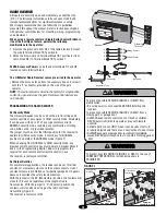
1
2 3 4 5 6 7 8 9 10 11 12 13 14 15 16 17 18 19 20
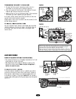
OPEN
CLO
SE
STO
P
OPEN
CLO
SE
STO
P
OPEN
CLO
SE
STOP
FRE
Q
FRE
Q
17
17
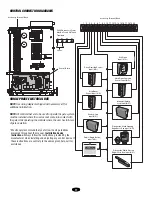
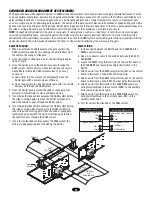
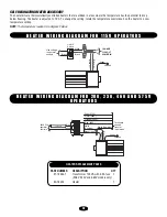
CONTROL CONNECTION DIAGRAMS
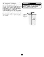
NOTE:
See wiring diagrams shipped with accessory kit for
additional information.
NOTE:
All controls that are to be used to operate the gate system,
must be installed where the user cannot come into contact with
the gate while operating the controls where the user has full view
of gate operation.
* We strongly recommend that you follow the UL guidelines
presented throughout the manual.
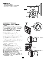
Installation device
instructions:
Always follow the instructions provided by the
manufacturer when installing and adjusting any control device. If
these instructions are contrary to the advice given here, call for
assistance.
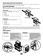
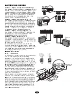
SINGLE PHASE ELECTRICAL BOX
Accessory Terminal Block
24VAC Accessory Power
May Be Found On These
Terminals
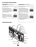
Control Board
Accessory Terminal Block
Close Override Control
Input (N.O.)
Stop/Reset
Control Input (N.C.)
Shadow Loop
Input (N.O.)
Radio (Single Button)
Input (N.O.)
Obstruction While Closing
Edge/Photo Eye Input (N.O.)
Obstruction While Opening
Edge/Photo Eye Input (N.O.)
Interrupt (Safety)
Loop Input (N.O.)
Hard Open Override
Control Input (N.O.)
Soft Open
Input (N.O.)
24Vac
Summary of Contents for LiftMaster Professional SL585
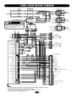
Page 32: ...32 T H R E E P H A S E S C H E M AT I C...
Page 39: ...39 N O T E S...


