


2
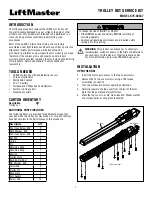
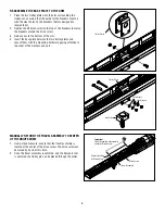
REMOVE THE LED CIRCUIT CARD
1. Unplug the J1 plug from the connector.
2. Remove the two LED circuit card mounting screws using a
T10 screwdriver or wrench.
3. Set the LED circuit card and mounting hardware aside in a
clean location.
REMOVE THE PASSPOINT ASSEMBLY TOP BRACKET
1. Remove the three Phillips head mounting screws that secure
the Passpoint assembly top bracket.
2. Lift the Passpoint assembly top bracket from the arm
assembly and set aside in a clean location, along with the
mounting hardware.
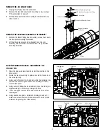
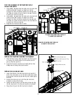
SLIDE RETAINING RING BACK, AND REMOVE THE
TROLLEY PIN
1. Press the bypass release lever to permit the rotation of the
drive screw.
2. Rotate the travel assembly to gain access to the free ends of
the retaining ring.
3. Using a set of fastener (E-ring) pliers, slide the retaining ring
towards the motor to gain access to the trolley pin that it
secures into place.
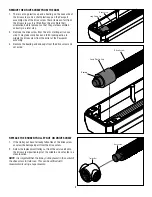
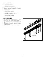
4. Using a small Phillips head screwdriver, press the trolley pin
approximately 1/4 of the way through the hole.
5. Press the bypass release lever, and rotate the drive screw
180 degrees.
6. Using needle nose pliers, remove the trolley pin and set it
aside into a clean location. (Drive screw can now be turned
without using the bypass release lever).
LED Circuit Card
Passpoint Assembly
Top Bracket
LED Circuit Card Mounting Screws
3 Phillips Head Mounting Screws
J1 Plug
LED Circuit Card Connector for J1 Plug
Switch Levers
Bypass Release Lever
Retaining Ring
over
Trolley Pin
Trolley Pin
Bypass Release Lever
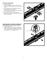
Retaining
Groove
Trolley Pin
Retaining Ring


