

CLOSE
EDGE
OPEN EDGE/
PHOTO
OPEN
PHOTO
CLOSE
PHOTO
CONTROL
INPUTS
FORCE
TIMER TO
CLOSE
OFF
MAX
OPEN
SINGLE BUTTON
RESET
STOP
SHADOW
INTERRUPT
CHGR
OVLD
CTRL PWR
CTRL
LOOP
INPUTS
GATE 2
ACCESSORY
POWER
ALARM
GATE 1
MAGR
SOL
GR
WH
YL
BL
RD
BR
GR
WH
YL
BL
RD
BR
12 V
GATE 2
SET
OPEN
LIMIT
SET
CLOSE
LIMIT
LEARN
LIMITS
GATE 1
LEARN
XMITTER
LOCK /
ON
OFF
PWR
OFF
MAX
SINGLE BUTTON
AC PWR
/SOLAR
BIPA RT DELAY
LOCK
GND
CTRL PWR
OFF
ON
AUTO OPEN
LOW BATT
Press and release the LEARN XMITTER button (LED will light).
Press the remote control button. The LED will flash and the alarm
output will activate twice.
A
E
G
D
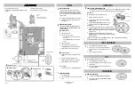
WIRING
FORCE ADJUSTMENT
PROGRAMMING
LEARN LIMITS
Use the SINGLE BUTTON to open and close the gate.
If the gate stops or reverses before reaching the fully open or
closed position increase the force by turning the force control
slightly.
Run operator through a complete cycle.
1
1
3
2
After any adjustments are made, test the operator:
Use the SINGLE BUTTON to open and close the gate.
Test the limits by making sure the gate is stopping at the OPEN
and CLOSE limits.
Test the force by making sure the gate will stop and reverse on
contact with an obstruction.
F
TEST
1
3
2
2
©2010 The Chamberlain Group, Inc.
01-35315B
All Rights Reserved
To protect against fire and electrocution:
• DISCONNECT power and battery BEFORE installing or servicing
operator.
For continued protection against fire:
• Replace ONLY with fuse of same type and rating.
B
POWER WIRING OPTIONS
This operator is capable of being powered by the
internal receptacle, an external receptacle or a solar
panel (not provided).
INTERNAL RECEPTACLE
Remove the access panel.
Connect AC power to the operator:
• Connect the green wire to the ground screw in the
access panel.
• Connect the black and white wires together with
wire nuts.
Replace the access panel.
Connect the wires from the transformer to the
AC PWR/SOLAR terminal located on the control board.
Plug the transformer into the internal receptacle.
EXTERNAL RECEPTACLE
Run low voltage wire between the transformer and the
operator.
Connect the wires from the transformer to the
AC PWR/SOLAR terminal located on the control board.
Plug the transformer into the external receptacle.
SOLAR PANEL
Not provided. See Accessories in the Installation Manual.
1
EARTH GROUND ROD
Install the earth ground rod within 3 feet of the operator.
Attach the ground wire to the ground terminal on the
control board.
1
C
CONNECT BATTERIES
1
2
Locate the battery plug.
Connect the battery plug to either connector on the control
board.
Use the proper earth ground rod for your local area. The
ground wire must be a single, whole piece of wire. Never splice
two wires for the ground wire. If you should cut the ground
wire too short, break it, or destroy its integrity, replace it with a
single wire length.
REMOTE CONTROLS
2
FORCE
OFF
MAX
SINGLE BUTTON
LEARN
XMITTER
SINGLE BUTTON
3
4
5
1
2
3
2
Press and hold the GATE 1 right button to move the gate to the desired
CLOSED position. When the gate is in the desired position, release the button.
NOTE:
The GATE 1 right and left buttons can be used to jog the gate back
and forth as needed.
When gate is in the desired CLOSED position, press and release the
LEARN LIMITS button. The control board will beep and the SET CLOSE LIMITS
LED will stop blinking.
Programming is now complete. (If the SET OPEN LIMIT LED continues to blink, repeat programming.) Test the limits by
pressing the SINGLE BUTTON to open and close the gate.
Close the gate. Make sure the operator arm is properly seated on the output shaft (the pin must fit into the slot). Make
sure the handle is released on the operator arm and the learn limit cam is touching the learn limit switch.
PROGRAM OPEN
Manually open the gate to the desired open position.
Tighten the handle on the operator arm.
Press and release the LEARN LIMITS BUTTON. The SET OPEN
LIMIT LED will blink.
Press and release the LEARN LIMITS button again. The control
board will beep and the SET CLOSE LIMITS LED will blink.
SINGLE GATE RIGHT-HAND SIDE
1
2
3
4
5
PROGRAM CLOSE
GATE 2
GATE 1
SET
OPEN
LIMIT
T
SET
CLOSE
LIMI
N
LEAR
LIMITS
A
B
C
Operator
Black
Black
Red
Red
Earth Ground Rod (Optional)
Battery (provided)
INTERNAL RECEPTACLE
SOLAR PANEL
(NOT PROVIDED)
EXTERNAL RECEPTACLE
Access Panel
D
E
F
G
Optional second 7AH, 12V battery
(not provided)
NOTE:
One 33AH battery (not provided)
can be used in place of the 7AH batteries.
Second Operator
(Optional)
Power Supply
Relay Adapter Module
Maglock
White
Black
Red
COM
NC
NO
Use the Dual Gate Wiring Kit (refer to the
accessory page of the installation manual).
POWER WIRING OPTIONS
a
b
c
120 Vac
6
7
Pin
Slot
Handle
Learn Limit Cam
Learn Limit Switch
Learn Limits Button
Gate 1 Right Button
a
b
c


