7 . ACCESSORIES AND OPTIONS
7.94
7.15.4 - Hitching an implement
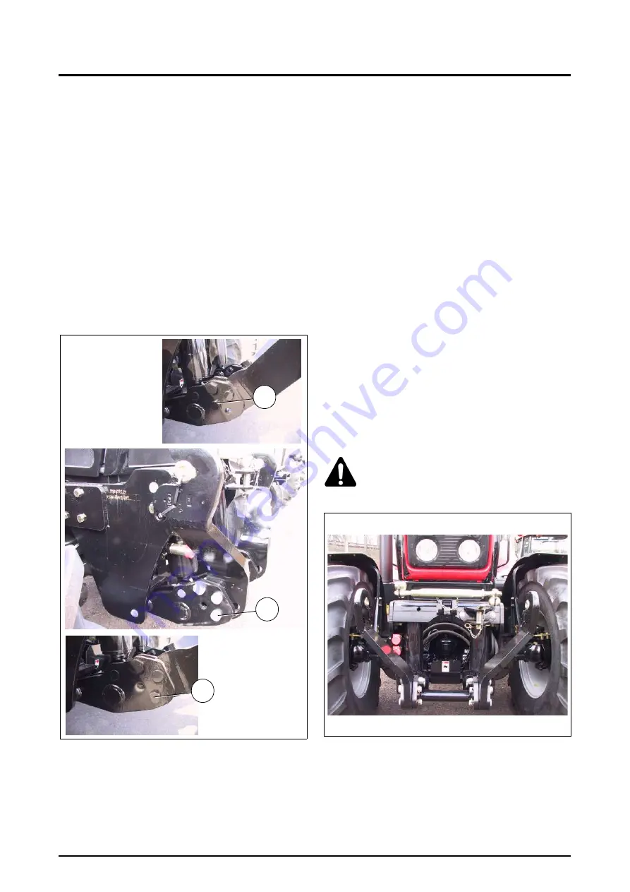
• Three positions can be used depending on require-
ments: Fixed, floating and transport position
(Fig. 234)
1. Fixed position
Position the arms horizontally and fit the pin in position
A.
2. Transport position
No hitched implement: Position the arms vertically to
reduce bulkiness and fit the pin in position B.
3. Floating position
Position the arms horizontally and fit the pin in position
C.
This position can be used to compensate for sloping
ground, thus allowing the implement to follow the nat-
ural lie of the land.
Example: Implement with one depth wheel to either
side of a roller.
• The linkage is fitted with automatic lower jaws, allowing
an implement to be hitched safely from the tractor cab.
Apply the following procedure when hitching an imple-
ment.
1. Move the lift arms to working position (fixed or float-
ing), and fit the hitch ball joints to the implement using
suitable stop pins.
2. Drive the tractor forwards towards the implement and
lower the lower arms.
3. Drive the tractor forwards to position the jaws under
the balls, and raise the lower arms carefully until the
jaws lock.
4. Tighten the handbrake and switch off the engine
before climbing out of the tractor.
5. Fit the third-point linkage, adjusting its length to set
the implement level, and couple the hydraulic unions
and universal joint if fitted.
6. Store implements on flat ground to keep them stable.
This makes hitching and unhitching easier.
Unhitching: carry out the operation in reverse order.
The external controls can also be used to adjust the link-
age.
• Storing the third-point linkage (Fig. 235)
Store the top link on its support when not in use.
7.15.5 - Driving on the road
• Controlling the active transport control system
This makes driving with lift implements at high speeds
more comfortable. It cannot be used for field work. Imple-
ment height cannot be adjusted when the transport control
system is operating.
To switch on the transport control system, lift the imple-
ment, leaving 40 to 50 mm of cylinder travel to allow the
transport control system to operate (release).
WARNING: The valves must be positioned at
“transport control system” (see decal) to
deactivate the spool valve action and avoid
accidental lowering of the implement.
• Maintenance
In addition to taking good care of equipment during use, it
should be maintained at regular intervals. This helps ensure
manufacture quality performance and reliability for a
number of years.
Regularly check the tightness of attachment screws, espe-
cially the first few times the linkage is used.
Fig. 234
B
Z2-404-03-04
P
A
Z2-419-03-04
Z2-418-03-04
Fig. 235
Summary of Contents for Techstar CVT MT525B Series
Page 2: ......
Page 4: ......
Page 5: ...1 TRACTOR IDENTIFICATION 1 1 Challenger MT500B EU 1 Chapter 1 TRACTOR IDENTIFICATION ...
Page 6: ......
Page 7: ...1 TRACTOR IDENTIFICATION 1 3 Challenger MT500B EU 1 CONTENTS 1 1 SERIAL NUMBERS 1 5 ...
Page 8: ...1 TRACTOR IDENTIFICATION 1 4 Challenger MT500B EU ...
Page 12: ......
Page 30: ......
Page 31: ...3 INSTRUMENTS AND CONTROLS 3 1 Challenger MT500B EU 3 Chapter 3 INSTRUMENTS AND CONTROLS ...
Page 32: ......
Page 34: ...3 INSTRUMENTS AND CONTROLS 3 4 Challenger MT500B EU ...
Page 51: ...4 OPERATION 4 1 Challenger MT500B EU 4 Chapter 4 OPERATION ...
Page 52: ......
Page 90: ......
Page 124: ......
Page 125: ...6 SPECIFICATIONS 6 1 Challenger MT500B EU 6 Chapter 6 SPECIFICATIONS ...
Page 126: ......
Page 128: ...6 SPECIFICATIONS 6 4 Challenger MT500B EU ...
Page 138: ......
Page 139: ...7 ACCESSORIES AND OPTIONS 7 1 Challenger MT500B EU 7 Chapter 7 ACCESSORIES AND OPTIONS ...
Page 140: ......
Page 235: ...8 TROUBLESHOOTING 8 1 Challenger MT500B EU 8 Chapter 8 TROUBLESHOOTING ...
Page 236: ......
Page 238: ...8 TROUBLESHOOTING 8 4 Challenger MT500B EU ...
Page 242: ......
Page 243: ...CONVERSION TABLES Challenger MT500B EU Appendix CONVERSION TABLES ...
Page 244: ......
Page 246: ......


