


A-12 - GENERAL INFORMATION
79019435B
GENERAL PRECAUTIONS
FOR DISASSEMBLY AND
RE-INSTALLATION
Before Operation
Always be safety-conscious in selecting clothes to wear
and suitable tools to use.
Before disassembly, be sure that you familiarize yourself
with the assembled condition for subsequent reference in
re-assembly.
Keep parts, and tools in proper order during operations.
When servicing electrically charged parts, be sure to dis-
connect the negative battery terminal.
To prevent oil or water leaks, use the liquid gasket as
required.
When reassembling disassembled parts, discard used
gaskets, O-rings, or oil seals and install new ones.
When lifting tip only the front or rear part of the tractor, be
sure to wedge the grounded wheels.
When the tractor is jacked up, be sure to support the
entire tractor with a stand. Lifting it up with jack only is a
dangerously unstable procedure.
When replacing parts, use authorized genuine Massey
Ferguson, AGCO and Challenger parts only. Massey
Ferguson, AGCO and Challenger assumes no responsi-
bility for accidents, operating problems or damage Caused
by the use of imitation parts. Also, the use of unautho-
rized parts will result in relatively poor machine perfor-
mance.
Precautions To Be Followed When Install-
ing Standardized Parts
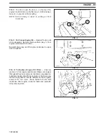
Roller or ball bearings
When a bearing is installed in a housing by the outer race,
use an installer, which is specially designed to push only
the outer race and vice versa.
The installer must be designed to install the bearing on
the shaft in a parallel position
When installing a bearing which appears the same on
both sides, install it so that the face which has the identi-
fication number faces in a direction for easy visual identi-
fication number faces in direction for easy visual identifi-
cation. All bearings which are to be installed in the trans-
mission case should be placed so that their identification
number faces outward.
If a shaft or a hole where a bearing is to be installed has
an inner seat the bearing should be pushed in completely
until it is seated.
Bearings should turn smoothly.
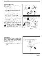
Oil seals
Oil seal installer should not deform the oil seals.
During installation, be careful not to damage the lips, and
assure that it is pushed in parallel to the shaft or hole.
When oil seals are installed, there should be no turnover
of the lips nor dislocation of the springs.
When a multi-lip seal is installed, the grooves between
lips should be filled with grease.
Use a lithium-based grease.
There should not be oil or water leaks past the new seals.
O-rings
O-rings should be coated with grease before installing.
Installed O-rings should have no slack or twist.
Installed O-rings should maintain proper tightness.