


Chapter 2
19
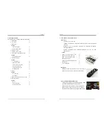
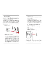
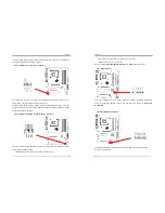
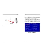
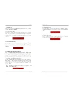
IDE 1/2 (IDE Hard-Disk Connector)
The motherboard has a 32-bit Enhanced PCI IDE and Ultra ATA66/100 controller
that provides PIO mode 0~4, Bus Master, and Ultra ATA66/100 function. This
connector is used for connecting 40 pins of ATAPI devices.
IDE 1 only connects two IDE devices. (
Primary
Master/Slave)
IDE 2 only connects two IDE devices. (
Secondary
Master/Slave)
Please refer to
Section 2-6 Serial ATA and Parallel ATA
for details.
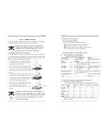
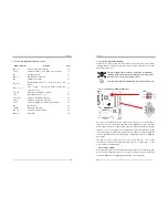
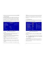
JP1 (CMOS Clear Jumper):
There is a CMOS RAM on board that has a power supply from external battery to
keep the data and system configuration. To clear the contents of the CMOS, please
follow the steps below.
1. Disconnect the system power supply from the power source.
2. Set the jumper cap at location [
2-3
] for <
5 seconds
>, and then set it back to the
default position.
Pin
Definition
1-2 Normal (default)
2-3 Clear CMOS Data
Chapter 2
20
3. Connect the system's power and then start the system.
4. Enter BIOS's CMOS Setup Utility and choose Load Setup Defaults. Type [
Y
] and
then press [
Enter
] to continue.
5. Set the system configuration in the Standard CMOS Setup menu.
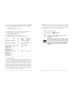
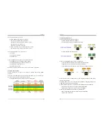
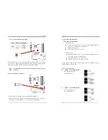
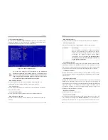
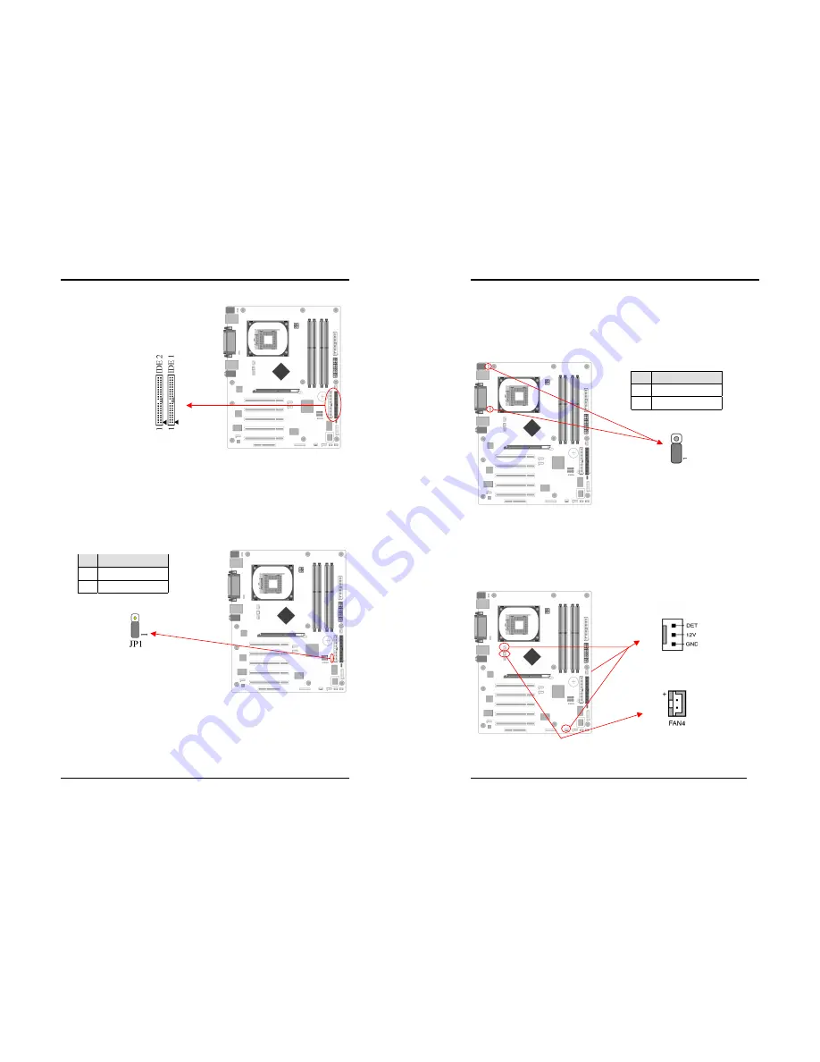
JP6/JP6A (Enable/Disable USB 0/1, 2/3 Device Power ON Jumper)
JP6 USB 0/1 JP6A USB 2/3
An USB keyboard hot key or an USB mouse-click can activate this board. To use
this function, select a hot key of your choice at the USB Resume from S3 option
under Wake Up Events in the BIOS's Power On Management screen. You must also
set this jumper's cap to pins
2-3
to use this function.
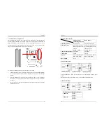
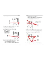
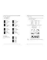
FAN1/2/3/4 (CPU/System/ North Bridge Cooling Fan Connectors):
The board's hardware management is able to detect the CPU and system fan speed in
rpm (revolutions per minute). The wiring and plugging may vary depending on the
Pin Definition
1-2 Disable
(default)
2-3 Enable


