CHAINTECH 7NIL1 User Manual Download Page 5

Chapter 2     


Chapter 2  Hardware Setup 

If your motherboard has already been installed in your computer you may still need 
to refer to this chapter if you plan to upgrade your system's hardware. 


This motherboard is electrostatic sensitive. Do not touch without 
wearing proper safety gadget and make sure to disconnect the power 
cable from the power source before performing any work on your 
motherboard. Not doing so may result in electrical shock! 

2-1  Installing a CPU Processor for Socket A 

The Socket A, designed for AMD® Athlon/Duron/XP processors, has been 
incorporated as a standard motherboard specification. To insert your CPU into 
Socket A please do the following: 

1.  Locate a cut edge on the top surface of the CPU close to one if it's corners. The 

same corner will also be cut off, leaving a noticeable notch in the CPU's corner.   
These markings indicate Pin 1 of the CPU.   

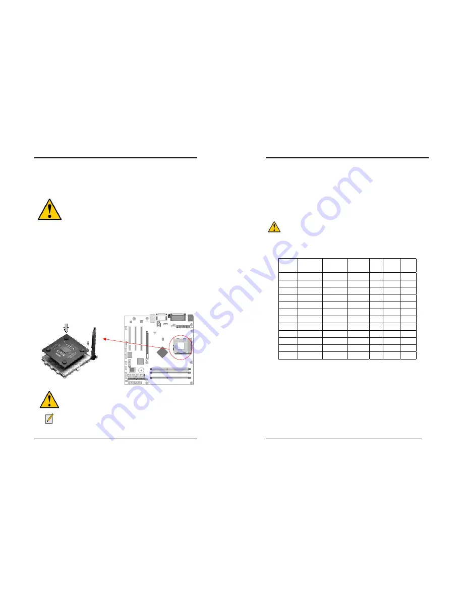
2.  Pull up the lever of Socket 462 so that it is perpendicular with the surface of the 

motherboard. Gently insert the CPU with Pin 1 at the same corner of Socket 462 
that contains the end of the lever. Allow the weight of the CPU to push itself into 
place. Do not apply extra pressure as doing so may result in damaging your CPU. 
Snap the lever back into place.   


Installing an AMD® approved heat sink with cooling fan is necessary for 
proper heat dissipation from your CPU. Failing to install these items may 
result in overheating and possible burn-out of your CPU. 


In order to boot up with a newly installed CPU, AC Power must be 
switched off before installation. 

Chapter 2   


2-2  Setting Your CPU’s Performance: 

Frequency Configuration: 

If you install a CPU on this motherboard, you must set the [

Front Side Bus


Frequency

JP25

 according to your processor (

See Section 2.4

). 


* CPU Speed = Multiplier x FSB Frequency 


AMD (K7) Duron CPU 


Model CPU 

Speed 

FSB


Frequency 

Multiplier Vcore 

L2   

Cache 

Micron 
process 

600 600 

MHz  100 

6.0  1.6V 

64KB 

0.18 

650 650 

MHz  100 

6.5  1.6V 

64KB 

0.18 

700 700 

MHz  100 

7.0  1.6V 

64KB 

0.18 

750 750 

MHz  100 

7.5  1.6V 

64KB 

0.18 

800 800 

MHz  100 

8.0  1.6V 

64KB 

0.18 

850 850 

MHz  100 

8.5  1.6V 

64KB 

0.18 

900 900 

MHz  100 

9.0  1.6V 

64KB 

0.18 

950 950 

MHz  100 

9.5  1.6V 

64KB 

0.18 

1.0G 1.0 

GHz  100 

10.0  1.6V 

64KB 

0.18 

1.1G 1.1 

GHz  100 

11.0  1.6V 

64KB 

0.18 

1.2G 1.2 

GHz  100 

12.0  1.6V 

64KB 

0.18 

1.3G 1.3 

GHz  100 

13.0  1.6V 

64KB 

0.18 


You do not need to make voltage settings because this board will automatically 
set your CPU voltage. 

Summary of Contents for 7NIL1

Page 1: ...tal device that complies with 47 CFR Parts 2 and 15 of the FCC Rules Operation is subject to the following two conditions 1 This device may not cause harmful interference 2 This device must accept any...

Page 2: ...s document is subject to change without notice and does not represent a commitment on the part of the vendor No warranty or representation either expressed or implied is made with respect to the quali...

Page 3: ...USB ports EHCI UHCI v1 1 compliant with over current protection Optional USB adapter for additional USB2 0 1 1 ports On board Super I O Controller ITE 8712 LPC I O with system monitors hardware Two U...

Page 4: ...Chapter 1 3 1 3 7NIL1 Motherboard Diagram Chapter 1 4 1 4 7NIL1 Motherboard Layout...

Page 5: ...e CPU to push itself into place Do not apply extra pressure as doing so may result in damaging your CPU Snap the lever back into place Installing an AMD approved heat sink with cooling fan is necessar...

Page 6: ...onfiguration This motherboards provides 3 184pin Double Data Rate DDR Dual Inline Memory Modules DIMM slots Which supports PC 1600 DDR200 PC2100 DDR266 PC2700 DDR333 and PC3200 DDR400 DDR SDRAM module...

Page 7: ...m including the power supply the keyboard and the various controllers on the front panel of the system case The power supply connector is the last connection to be made while installing a motherboard...

Page 8: ...the poly fuse will return to its normal state Then the keyboard or USB connector can function properly again Unlike conventional fuses the poly fuse does not have to be replaced relieving the user was...

Page 9: ...nd then press Enter to continue 5 Set the system configuration in the Standard CMOS Setup menu Pin Definition 1 2 Normal default 2 3 Clear CMOS Data Chapter 2 14 JP5 Keyboard Power On Function Jumper...

Page 10: ...s cap setups up the CPU Ext Clock Frequency 1 2 The default value is 133 166 MHz The will allow the CPU s Ext Frequency and memory frequency to be adjusted through the BIOS 2 3 Set 100 MHz at CPU Ext...

Page 11: ...ouse is touched The system resumes in different ways as defined by Power Management Setup screen in BIOS 4 RESET System Reset Switch Connector This connector should be connected to the reset switch on...

Page 12: ...es WOL capability to the motherboard CN5A WOM Wake on Modem Connector The Wake Up On Modem selection in BIOS s Power Management Setup Menu must be enabled to use this function This header is used to c...

Page 13: ...tains a USB Host controller and includes a root hub connector for optional USB Adaptor USB 2 3 and 4 5 Chapter 2 22 CN24 Front Audio Connector This connector give you the option of a front panel audio...

Page 14: ...can retain the setup information even when the power is turned off To enter the Phoenix Award BIOS setup program press the Delete key when you Power on or reboot the computer system The primary screen...

Page 15: ...s called POST Power On Self Test This function stops the computer if BIOS detects a hardware error You can tell BIOS to halt on all errors no errors or not to halt on specific errors Chapter 3 26 3 2...

Page 16: ...essed and held down 3 Typematic Delay Msec The typematic delay sets how long after you press a key that a character begins repeating Security Option The Supervisor and or User Password functions shown...

Page 17: ...ows Optimal Select this option will let the system automatically detect its performance Aggressive Select this option for a better system performance It increases a bit of the system performance Memor...

Page 18: ...rmation on setting peripheral devices By choosing the Integrated Peripherals option from the CMOS Setup Utility menu Figure 3 1 the screen below is displayed This sample screen contains the manufactur...

Page 19: ...able options are 3F8 IRQ4 2E8 IRQ3 3E8 IRQ4 2F8 IRQ3 Disabled and Auto 3 UART Mode Select This function allows you to select an operating mode for the second serial port Available options are Normal I...

Page 20: ...buffer and the monitor s electron gun turns off This function requires a monitor with Green features in order to take advantage of the power saving function If you enable this function and do not hav...

Page 21: ...from the CMOS Setup Utility menu Figure 3 1 the screen below is displayed This screen contains the manufacturer s default values for the motherboard Figure 3 7 PNP PCI Configurations Reset Configurati...

Page 22: ...quency Voltage Control By choosing the Frequency Voltage Control option from the CMOS Setup Utility menu Figure 3 1 the screen below is displayed This sample screen contains the manufacturer s default...

Page 23: ...et to Setup a password is required to enter BIOS and change BIOS settings When the Security Option function is set to System a password is required to enter both BIOS and the computer s operating syst...

Page 24: ...up 1 Please select Nvidia Driver Package to begin installation 2 Please click NEXT to start installation Chapter 4 44 3 Please click OK to continue 4 Please click NEXT to continue 5 If you want to ins...

Page 25: ...es I want to restart my computer now then Please Click OK to restart you computer If you do not want to restart your computer select No I will restart my computer later then click OK to continue Chapt...

Page 26: ...e install the C Media Audio driver 4 Please click Next to continue install the C Media Audio driver Chapter 4 48 5 Please click Next to continue install the C Media Audio driver 6 Please click Next to...

Page 27: ...ontinue 4 3 USB 2 0 Driver Setup By Choosing USB 2 0 Driver from the main menu it will provide the informations that you require to install the USB 2 0 Drive USB 2 0 only support Windows 2000 XP opera...

Page 28: ...y diskette has only one BIN file to avoid confusion AwardBIOS Flash Utility V X XX C Phoenix Technologies Ltd All Right Reserved For XXXX XXXXXX XXXXXXXXXX X DATE XX XX 2002 Flash Type XXXXXX XXXXXXXX...

Reviews: