


Installation & Operation Manual Merlin 1500S
Rev: 1 01-21
10
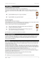
EM Stop
If an emergency shut off button (either remote or on the panel) is pressed, the LED will illuminate and
the gas is shut off. The button(s) must be re-set before restarting the system.
OFF = OK
ON = Emergency Shut Off button pressed
Gas Detected
Under normal working conditions this LED is off.
If an external Merlin detector connected detects high levels of gas this LED will illuminate and the Gas
valve will turn off.
OFF = OK
ON = Gas detected.
CO
2
High
Under normal working conditions this LED is off.
If the concentration of Carbon Dioxide (CO
2
) in the air is at alarm level (CO2 Monitors sold
separately), the LED will show illuminate and the Gas valve will turn off.
OFF = OK
ON = the concentration of CO
2
is at alarm level.
CO
2
Mode
The ‘CO
2
Mode’ button located on the front of the panel will only be available to use when ‘Fan fault’ LED
illuminates. To enable CO
2
Mode, this button has to be pressed for 5 seconds. The Fan Fault LED will go
off and CO
2
Mode LED will come on. In this mode, the Merlin 2000S will monitor only the CO
2
levels to
ensure there is a safe working environment and allow the gas valve to open for 8 hours each time CO2
Mode is activated provided CO
2
levels are safe.
At the end of 8 hours, the gas valve will close and CO
2
Mode LED will be flashing.
To reinstate the system the panel has to be restarted.
CO2 Mode will be permanently disabled if a CO2 monitoring device is not connected.


