background image

Installation & Operation Manual                                                                                               Merlin 1500S 


Rev: 1    01-21 

4  

Installation 

   Planning 


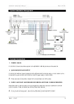
The Merlin 1500S acts as an interlock between the ventilation system and the gas solenoid valve. It 

ensures the gas solenoid cannot be opened unless the ventilation system is proven to be working and 
working at such a speed that is effective to exhaust the fumes from the appliances. 

 
The fans can be monitored through air pressure switches or by means of an additional current monitor. 

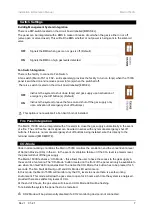
To operate the Merlin 1500S the fans should be turned to the ‘on’ position, once the panel receives a 
signal to indicate the fans are operating the key on the panel can be turned to the ‘on’ position and this 
will open the gas solenoid valve. If the fans should fail, the ‘fan fail’ LED on the panel will illuminate and 
the gas solenoid will close.  
 
The Merlin 1500S can work in conjunction with carbon dioxide, natural gas, carbon monoxide and 
LPG sensors.  


Please refer to your detector manual for important information regarding coverage, location and 
positioning including areas and conditions to avoid. 


   Mounting 


Place the panel 48-60 inches above finished floor level. 


Unpack all the parts! 
Designed for surface mounting, it must be installed by a 
licensed, insured contractor. 


1.


Carefully remove the front cover from the unit by 
unscrewing the four bolts located at each corner.  
To do this – use the socket wrench provided. 

2.


Mark the four screw holes located on the back of the enclosure to the wall. Ensure the wall surface is 
flat to prevent base distortion. 

3.


After executing the mounting and the connections – replace the front cover and insert the security 
caps over the four bolts. 


Take care when making connections to high voltage connectors! 


Any damage attempting to remove the circuit board may void any warranty! 


All Class 2 wiring is to be installed within flexible tubing to maintain segregation between circuits! 


Wiring of different circuits shall be separated by means of routing, clamping or barrier! 


A flush mount kit is available, comprising of a mounting bracket and decorative surround strip. Contact 
your supplier for more information. 


Summary of Contents for Merlin 1500S

Page 1: ...here is no need for gas pressure proving The Merlin 1500S acts as an interlock between the ventilation system and the gas solenoid valve It ensures the gas solenoid cannot be opened unless the ventilation system is proven to be working and working at such a speed that is effective to exhaust the fumes from the appliances The information contained within this manual should be referenced for typical...

Page 2: ...4 Planning 4 Fixing Mounting 4 Typical Installation Arrangement 5 Terminal Connections 5 Switch Settings 7 Fire Panel Integration 7 CO2 Mode 7 General Specification 8 Operation 9 First Power Up 9 Emergency Shut Off Button 9 LED Indicators 9 CO2 Mode 10 Maintenance 11 Cleaning 11 Bump Test Gas Response Check 11 ...

Page 3: ...sing out of this sale including but not limited to the implied warranties of description merchantability and intended operational purpose are limited in duration to the above warranty period In no event shall the manufacturer be liable for loss of use of this product or for any indirect special incidental or consequential damages or costs or expenses incurred by the consumer or any other user of t...

Page 4: ... for important information regarding coverage location and positioning including areas and conditions to avoid Mounting Place the panel 48 60 inches above finished floor level Unpack all the parts Designed for surface mounting it must be installed by a licensed insured contractor 1 Carefully remove the front cover from the unit by unscrewing the four bolts located at each corner To do this use the...

Page 5: ...ctor using a 3 core cable can be connected to a gas solenoid valve which can shut the gas supply on alarm status Pressure sensors should be screwed to the downstream port of the valve 3 SUPPLY EXTRACT FAN PRESSURE DIFFERENTIAL SWITCHES CURRENT MONITORS These terminals are used to receive an input signal from external air pressure switches or external current monitors These terminals have factory f...

Page 6: ...P or similar 6 GAS DETECTOR Connections can be made for a Merlin gas detector LPG NG CO or Hydrogen If no detector is being used leave the factory fitted link in A wiring example is shown Refer to your gas detector manual for further information 7 FAN SWITCHES This terminal switches when the key is turned on and off This can be connected to a fan switch supplied separately which can provide power ...

Page 7: ...rm to close the gas supply automatically in the event of a fire The volt free fire alarm signal can be wired in series with any remote emergency shut off buttons If there are no remote emergency shut off buttons being installed wire this directly to the terminal marked EM REMOTE CO2 Mode Under normal working conditions the Merlin 1500S monitors the ventilation and the concentration level of Carbon...

Page 8: ...oid Valve Output 110 120VAC Current Consumption 12W max 50mA 120VAC Internal Fuse 3 15A Operating Temperature 32 104 F 0 95 RH Non Condensing Audible Alarm Buzzer dB 65 dB 300mm distance in quiet conditions Internet connection N A Housing Material Polylac PA 765 Flame Rating UL 94 UL Approval Reference E464760 O All Dimensions H x W x D mm inch 7 08 x 10 x 3 03 ...

Page 9: ...h is turned on the Merlin 1500S will open the gas valve and the Gas On LED will illuminate Supply Fans Under normal working the LED will illuminate If a supply fan fault is detected the LED will flash ON OK FLASHING One of the supply fans is not running IF SUPPLY AND OR EXTRACT FANS LED FLASHES FOR MORE THAN 20 SECONDS THE GAS WILL SHUT OFF Extract Fans Under normal working the LED will illuminate...

Page 10: ...vel CO2 Monitors sold separately the LED will show illuminate and the Gas valve will turn off OFF OK ON the concentration of CO2 is at alarm level CO2 Mode The CO2 Mode button located on the front of the panel will only be available to use when Fan fault LED illuminates To enable CO2 Mode this button has to be pressed for 5 seconds The Fan Fault LED will go off and CO2 Mode LED will come on In thi...

Page 11: ...m fails to operate as intended in an alarm state the gas detector must not be used until a full inspection and service has been conducted Why is it important A detector may visually appear in good working order but its sensitivity can be inhibited by external factors Dust humidity temperature fluctuations cleaning products contaminants or sensor drift ageing can cause a decline in sensitivity and ...

Page 12: ...to the system owner or system user Date of Installation Installation Location Organisation Stamp Signature of the installer Canadian Gas Safety info canadiangassafety com Telephone 647 577 1500 Canadian Gas Safety is the owner of this document and reserves all rights of modification without prior notice ...

Reviews: