Chapter XIV Logic Analyzer (Option)
172
Chapter XIV Logic Analyzer (Option)
The 4456 series provides the logic analyzer hardware option. The logic analyzer system and oscilloscope system
are organically combined, which use the common horizontal system, trigger system and measurement system,
provide cursor measurement and parameter measurement for digital signal, and can help you solve the design and
analysis problems of analog-digital signal quickly. For details of the horizontal setting of logic analyzer, see
Chapter IV
“
Horizontal System
”
, for details of the trigger setting, see Chapter V
“
Trigger System
”
, for details of
the parameter measurement, see Chapter VI
“
Measurement System
”
.
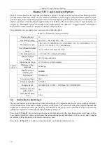
The parameters of logic analyzer are as shown in the following Table:
Table 14.1 Parameters of Logic Analyzer
Logical
analyzer
Digital channels
16
Threshold grouping
Pod 1: D7 ~ D0, Pod2: D15 ~ D8
Threshold selection
TTL (1.4 V), 5VCMOS (2.5 V), 3.3VCMOS (1.65 V), 2.5VCMOS (1.25 V),
ECL (-1.3 V), PECL (3.7 V), user-defined
User-defined threshold
range
±20 V, with an increment of 10 mV
Threshold precision
± (150 mV+3% of threshold setting)
Maximum input
voltage
±40 V peak-peak value
Input dynamic range
±10 V relative to the threshold
Minimum voltage
amplitude
400mVpp
Maximum input
switching rate
400MHz
Termination
100 kΩ±1%
Vertical resolution
1bit
Timing sample rate
2.5 GSa/s
Memory depth
500 Mpts/CH
(
C/D/E
)
、
200 Mpts/CH
(
CM/DM/EM
)
Minimum detection
pulse width
2ns
Inter channel delay
error
3.2ns
14.1
Enable/disable digital logic
The logical analyzer option supports waveform color display of 16 digital channels, and you can change the height
of each channel waveform and its display position on the screen. You can also flexibly group digital channels and
display them with labels. After the grouping, all channels in the group can be positioned, so as to shorten the
setting time required for traditional channel positioning one by one.
Press down
【
Digital
】
key in the Function Area on the front panel, and the logic function menu will pop up (if no
logic analyzer hardware option is purchased, the corresponding prompt information will be given), and 16 digital
waveforms will be displayed in the waveform window area.
Press down
【
Digital
】
key again to close the digital waveform and function menu.
Summary of Contents for 4456 Series
Page 10: ...VIII...
Page 55: ...Chapter V Trigger System 45 Fig 5 51 RF Test Signal Example...
Page 69: ...Chapter VII Mathematical Operation 59 Fig 7 10 Advanced Math Example...
Page 71: ...Chapter VIII Display System 61 Fig 8 3 Wfm Palette Menu Fig 8 4 Normal Palette...
Page 72: ...Chapter VIII Display System 62 Fig 8 5 Inverted Palette Fig 8 6 Temperature Palette...
Page 75: ...Chapter VIII Display System 65 Fig 8 12 XY Display Example...
Page 165: ...Chapter XI Protocol Analyzer Option 155 Fig 11 242 1553 Trigger and Analysis Example...


