background image

If the alternator system fails, the MASTER switch may be set to the OFF position to preserve 
Main Battery capacity for later in the flight. With the MASTER switch OFF and the STBY 
BATT switch in the ARM position, the standby battery will power the Essential Bus for a 
limited time. Time remaining may be estimated by monitoring Essential Bus Voltage. At 20 
Volts, the standby battery has little or no capacity remaining. 

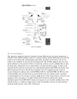
The aircraft’s electrical system status is displayed to the crew via the voltmeter, ammeter, and 
annunciators. Normal bus voltages with the alternator operating shall be about 28 volts. When 
the voltage for either Main or Essential is at or below 24.5 volts, the numeric value and 
VOLTS text turns red along with the "LOW VOLTS" annunciation. This is an indication that 
the alternator is not supplying all the power that is required by the aircraft. (Indicated voltages 
between 24.5 and 28 volts may occur during low engine RPM conditions). 

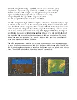
Electric current (AMPS) indication for both the main and Standby batteries is provided at the 
bottom of the EIS ENGINE or SYSTEM pages, labeled "M BATT S". Main battery current is 
displayed below the "M". Standby battery current is displayed below the "S". A positive 
current value (shown in white) indicates that the battery is charging. A negative current value 
(shown in amber) indicates that the battery is discharging. In the event the alternator is not 
functioning or the electrical load exceeds the output of the alternator, the main battery 
ammeter indicates the main battery discharge rate. 

In the event that Standby battery discharge is required, normal discharge should be less than 4 
Amps. After engine start, with the STBY BATT switch in the ARM position, the Standby 
Battery ammeter should indicate a charge showing correct charging of Standby Battery 
System. 

Ignition System. 

The engine is provided with two independent ignition systems. The two engine driven 
magnetos are independent from the power supply system, and are in operation as soon as the 
propeller is turning and the ignition switch is not off. This ensures safe engine operation even 
in case of an electrical power failure. When the MAGNETOS switch is rotated to the spring 
loaded START position, (with the master switch in the ON position), the starter contactor is 
closed and the starter, now energized, will crank the engine. When the switch is released, it 
will automatically return to the BOTH position. 

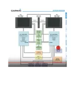
 G1000 System (and other avionics). 

The C172S avionics include a G1000, KAP 140 autopilot, and standby airspeed, altimeter, and 
attitude indicators.
The G1000 is comprised of several main components: 
Primary Flight Display (PFD, left) and Multi-Function Display (MFD, right) 
Audio panel (also supplies connection between PFD & MFD for revisionary mode)
2 Avionics Units (each supplies both GPS and VHF information to G1000)

Summary of Contents for C172S Nav III

Page 1: ...C172S Nav III Training Manual Crosswinds Aviation 1st Edition...

Page 2: ...g procedure Flaps 20 FULL 17 Maneuver standards 10 5 1 3x Vso approach touchdown within 400 of selected point 17 Short field Landing procedure Flaps FULL 18 Maneuver standards 10 5 1 3x Vso approach t...

Page 3: ...n oil containers and risk contamination The engine has a full pressure wet sump type lubrication system Oil is drawn from the sump through an oil suction strainer screen into the engine driven oil pum...

Page 4: ...left of the flap switch indicates flap travel in degrees The wing flap system circuit is protected by a 10 ampere circuit breaker labeled FLAP on the left side of the control panel Pitot static system...

Page 5: ...eservoir tank fuel flows through the auxiliary fuel pump past the fuel shutoff valve through the fuel strainer to an engine driven fuel pump From the engine driven fuel pump fuel is delivered to the f...

Page 6: ...ling on the left firewall The alternator and battery are controlled through the MASTER switch ALT and BAT found near the top of the pilot s switch panel Power is supplied to most electrical circuits t...

Page 7: ...in amber indicates that the battery is discharging In the event the alternator is not functioning or the electrical load exceeds the output of the alternator the main battery ammeter indicates the ma...

Page 8: ...reference lines and the magenta line that appears above the heading indicator to identify a standard rate or half standard rate turn Outside air temperature OAT displays on PFD under the airspeed tape...

Page 9: ......

Page 10: ...Empty Weight Maximum Ramp Weight 2558lbs Maximum Take off weight weight 2550lbs Speed KTS Description Airspeed indicator markings Vso 40 Stall speed in landing configuration Vs 48 Stall speed with ze...

Page 11: ...all in the center HSI DG aligned with the compass Compass no cracks no leaks no bubbles deviation card present Flight instrument check during taxi Turn coordinator indicating a turn Inclinometer Ball...

Page 12: ...Mixture to cutoff Fuel selector magnetos and battery master off Touchdown at lowest speed possible...

Page 13: ...t rudder as required for turning tendencies 5 Airspeed Alive 6 Start smooth rotation at 55 KIAS 7 Accelerate to 74 KIAS VY 8 After Takeoff Checklist 1 000 AGL 1 Line up on centerline 2 Smoothly apply...

Page 14: ...rotate at 51 KIAS or as calculated with performance charts 9 Accelerate to 56 KIAS Vx or as calculated with performance charts 10 Clear of obstacles flaps cruise 11 Accelerate to 74 KIAS VY 12 After T...

Page 15: ...west possible airspeed remain in ground effect 6 In ground effect accelerate to 62 KIAS begin climb 7 Clear of obstacles flaps Cruise 8 Accelerate to 74 KIAS VY 9 After Takeoff Checklist out of 1 000...

Page 16: ...t on the landing runway It is based on the pilot s judgment of certain visual cues and depends on a constant final descent airspeed and configuration FAA H 8083 3A p 8 7 Approach Gust factors Slightly...

Page 17: ...touchdown point on extended base or on extended final when ready to descend out of pattern altitude Reduce power to 1700 and select flaps 10 6 Descend out of TPA at 90 KIAS 7 Turn base approx 45 degr...

Page 18: ...t of pattern altitude Reduce power to 1700 and select flaps 10 6 Descend out of TPA at 90 KIAS 7 Turn base approx 45 degrees from touchdown point slow to 80 KIAS and select flaps 20 8 Select flaps FUL...

Page 19: ...ttern altitude Reduce power to 1700 and select flaps 10 6 Descend out of TPA at 90 KIAS 7 Turn base approx 45 degrees from touchdown point slow to 80 KIAS and select flaps 20 8 Select flaps FULL and m...

Page 20: ...n the downwind 5 When abeam touchdown point power to idle 6 Adjust pitch to maintain appropriate glide speed 7 Plan and maneuver to execute a safe approach and landing 8 Use flaps 0 FULL as necessary...

Page 21: ...tended base or on extended final when ready to descend out of pattern altitude Reduce power to 1700 and select flaps 10 6 Descend out of TPA at 90 KIAS 7 Turn base approx 45 degrees from touchdown poi...

Page 22: ...lout 5 From straight and level coordinate aileron and rudder to roll into a 45 o bank 6 Add a small amount of power 100 200 RPM as you roll through 30 o of bank 7 Maintain altitude and airspeed 8 Refe...

Page 23: ...rspeed that is 5 to 10 knots above published Vso 12 Maintain directional control using outside visual references and inside instrument references 13 Practice gentle climbs descents and turns at consta...

Page 24: ...ts NOTE Minimum safe altitude for this maneuver is 1500 AGL Crosswinds Aviation requires a minimum altitude of 3 500 AGL Power Off stalls are performed in the landing Configuration 1 Perform clearing...

Page 25: ...neuver 45 to the downwind with the first circuit to the left Downwind 1 Roll wings level parallel to the boundary 2 Maintain distance about 1 2 mile from boundary 3 At field boundary edge turn first c...

Page 26: ...st turn to the left at the highest groundspeed and steepest bank angle max 45 degrees 11 Bank angle will gradually need to be decreased to the upwind point slowest groundspeed 12 From the upwind point...

Page 27: ...est bank angle not to exceed 30 degrees 8 Directly crosswind moderate bank angle and decrease as the airplane turns upwind 9 Maintain coordinated flight throughout 10 Cross the line feature with wings...

Page 28: ......

Page 29: ...ts The C172S has an aluminum propeller A True B False How many AMP breaker protects the flap motor A 10 B 15 C 20 How many volts is the C172S electrical system A 12 B 14 C 28 What would an illuminated...

Page 30: ...7kts C 20kts The C172S requires the AHRS to be operative for VFR flight A True B False Brake fluid is what color A Red B Clear C Yellow List all the V speeds for the C172S For every 1 000 of altitude...

Page 31: ...B False...

Reviews: